
Whatever routing protocol is running between the PE and CE will need to be redistributed into BGP, since BGP is the only protocol that supports the VPNv4 routing table. The BGP routes will also need to be redistributed into the PE/CE routing protocol.
From the PE perspective, we’ll need the VRFs set up on the interfaces and on the routing protocols. For the sake of labbing, we’ll use the same LAN subnets on both customers.
Customer A:
Loopback 101 – 192.168.101.0/24
Loobback 102 – 192.168.102.0/24
Customer B:
Loopback 101 – 192.168.101.0/24
Loobback 102 – 192.168.102.0/24
The config sequence will be:
- Configure CE routers:
- Loopbacks to represent local segments.
- Interface Gig0/0
- Routing protocol
- Configure MPLS Unicast Routing
- EIGRP on MPLS core.
- Enable MPLS globally and on interfaces.
- Configure PE routers:
- VRF config.
- Outside interface config: VRF and routing protocols.
- MP-BGP config.
CE Router Config
R7:
inter loo 101
ip add 192.168.101.1 255.255.255.0
router ospf 7
network 10.17.0.0 0.0.0.255 area 0
network 192.168.101.0 0.0.0.255 area 1
R8:
inter loo 102
ip add 192.168.102.1 255.255.255.0
router ospf 8
network 10.48.0.0 0.0.0.255 area 0
network 192.168.102.0 0.0.0.255 area 2
R9:
inter loo 101
ip add 192.168.101.1 255.255.255.0
router eigrp 9
network 10.19.0.0 0.0.0.255
network 192.168.101.0 0.0.0.255
R10:
inter loo 102
ip add 192.168.102.1 255.255.255.0
router eigrp 10
network 10.40.0.0 0.0.0.255
network 192.168.102.0 0.0.0.255
MPLS Unicast Routing Config
For details on this config, check the MPLS Operations post.
PE Router Config
Up until this point, it’s just been basic config. The PE routers will take a little more thought. I’ll put comments in line so I can remember what I’m doing.
R1:
! Define our VRFs. This should be easy, and can be copied to both PE routers without changing.
vrf definition CUS_A
! We need the route distinguisher to uniquely identify prefixes inside the MPLS business.
rd 100:78
address-family ipv4
! We need these extended community attributes in BGP to translate from the unique VPNv4 prefix, 100:78:192.168.101.1, to the IPv4 prefix, 192.168.101.1, for BGP.
route-target export 100:78
route-target import 100:78
vrf definition CUS_B
rd 100:910
address-family ipv4
route-target export 100:910
route-target import 100:910
! Set up vrf forwarding on the interfaces facing the CE routers. Remember, these are not MPLS interfaces. Again, nothing too terrible here, just standard VRF config.
interface gig0/1
vrf forwarding CUS_A
ip add 10.17.0.1 255.255.255.0
interface gig 0/3
vrf forwarding CUS_B
ip add 10.19.0.1 255.255.255.0
! Set up the routing protocols. The redistribution is the only thing to be careful about until we get to the BGP setion.
router ospf 7 vrf CUS_A
network 10.17.0.0 0.0.0.255 area 0
redistribute bgp 100
router eigrp CUS_B
address-family ipv4 unicast vrf CUS_B autonomous-system 9
! It took me a minute to find the redistribute command. It’s under the topology subsection.
topology base
! Don’t forget, for redistributing into EIGRP you have to include the metric info.
redistribute bgp 100 metric 100 1 255 1 1500
router bgp 100
neighbor 10.4.4.4 remote-as 100
neighbor 10.4.4.4 update-source loopback 0
! This next command is the key to setting up the VPNv4 routing.
address-family vpnv4
neighbor 10.4.4.4 activate
address-family ipv4 vrf CUS_A
redistribute ospf 7
address-family ipv4 vrf CUS_B
redistribute eigrp 9
All in all, this isn’t too bad. A lot of basic config for routing and vrfs. The MPLS part is pretty simple, just the ldp router-id and then enabling it on the interfaces. Then the big twist at the end is just doing the activate command under bgp address-family vpnv4. When you break it down into parts, it’s easy stuff.
But how does it work?
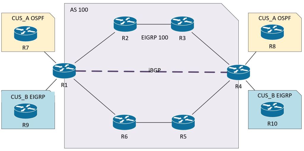
How are all of these components working together? We’ll need to follow the path of the packet through the network to see it in action. Let’s follow a ping from Customer A’s 192.168.101.1 (R7 Loopback 101) to Customer A’s 192.168.102.1 (R8 Loopback 102).
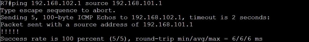
First let’s confirm that a ping will actually succeed.
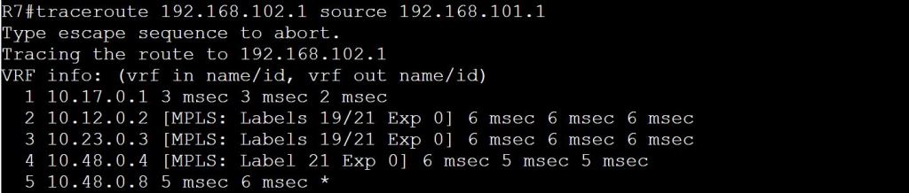
Now let’s see the details with a traceroute. We can see that we’ve got some MPLS going on there. Also, 10.48.0.8 is interface gig 0/0 on R8.
The first hop is pretty straightforward. It’s just an OSPF route learned from R1. It’s an E2 route because it’s coming from a different area, Area 0.

Hopping over to R1, we know we can’t just do a show ip route, because the only thing in the global routing table will be those EIGRP 100 routes, plus the connected routes. A show ip route vrf CUS_A should get us started.
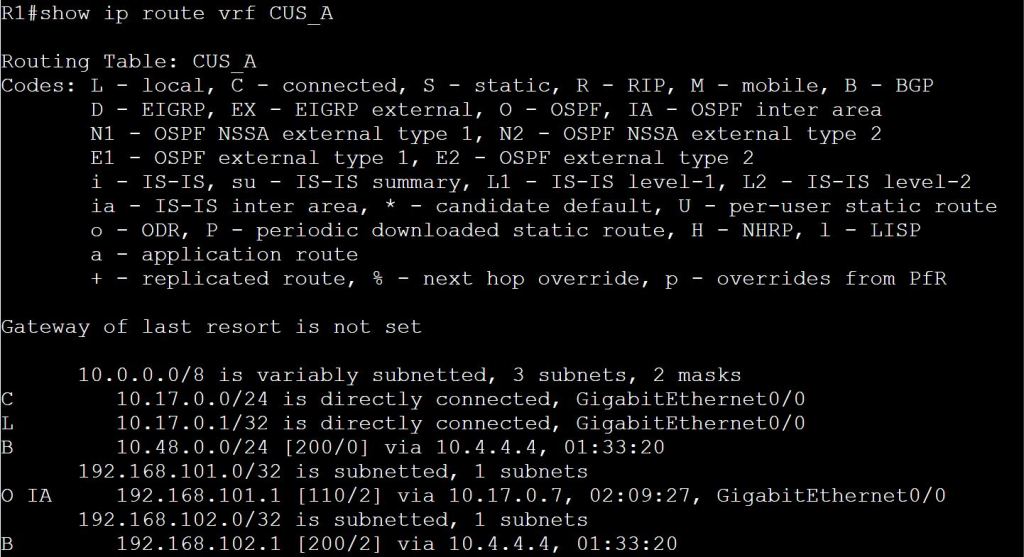
So we learned from BGP that to get to 192.168.102.1, we’ll need to take 10.4.4.4. The only problem is, how do we get to 10.4.4.4? There’s no route here for that! Luckily we have MPLS configured. Let’s do a show mpls forwarding-table.
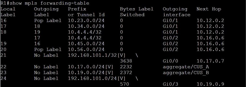
We know from our traceroute that the packet went to 10.12.0.2 next. We can also see the labels listed as 19/21. Label 19 makes sense, as this table above shows 10.4.4.4/32 with Outgoing Label 19, and a next hop of 10.12.0.2. Where does 21 come into play? Let’s check the MPLS table on R2.
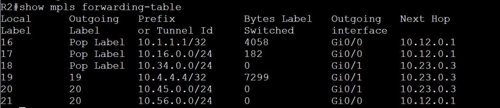
We see here that R2 needs to swap the label 19 (Local Label) for 19 (Remote Label). Again, it’s ok that they use the same label. But the swap still has to happen. The question still remains, where the hell is this mystery 21 label? We see it again on the 3rd hop of the original traceroute, 19/21. It’s almost like there’s a 21 getting stacked in there… Let’s check R3.

R3 knows how to get to 10.4.4.4 via 10.34.0.4, but it also knows to pop the label before sending, since R4 is the egress LSR. Still no label 21 though! Let’s take a look at R4.

With a show ip cef we can finally understand the mystery of that 19/21 label stack in the traceroute. This whole bit probably belongs under the MPLS Traceroute section, but it’s still relevant here.
There’s another missing piece here. We know how MPLS works with the label swapping, but what we’re not seeing is how R4 knows which VRF to route the packet through. The MPLS traffic is coming to R4 on a global interface, Gig 0/0. And we know that R4 has two customers with 192.168.102.1 IP addresses, so how can R4 figure out which one to use?
The solution is to add another label to the MPLS stack. The top label is the regular MPLS label for getting from one PE to the other. The bottom label (usually) tells the egress PE what the next hop should be. The PE can figure it out from there which VRF that should be.
The top label is distributed by LDP from neighbor to neighbor, swapped or popped accordingly. The bottom label (the VPN label) is shared from PE to PE using MP-BGP.
