This is a pretty important topic when we get to the DNAC section, so we may as well get it out of the way. For background trivia, the “lite” part means that we’re VRFs without MPLS label imposition or without MP-BGP extensions. And it’s fewer calories.
References:
MPLS and VPN Architectures, Volume II (Cisco Press)
Note: Regarding naming the VRFs, I’ve typically used a descriptive name which is what is usually used in example configs, such as “CAMPUS” and “LAB”. But then I started naming them to match the Virtual Network names in DNAC, which makes sense for readability and mapping to the corresponding VLANS. However, after messing with SD-WAN, they just slap a number on there and I’ve found that to be super easy to work with when doing pings, etc. So I’m going to stick with numbers for now and hopefully they’ll be logically mapped later to DNAC VNs without being too confusing.
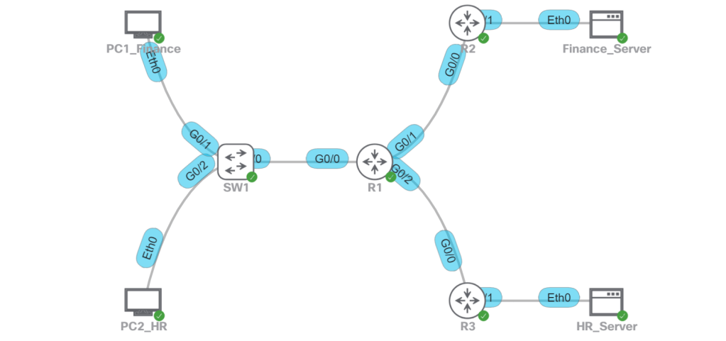
The idea for this setup is that we don’t want Finance users talking to the HR server, and we don’t want HR users talking to the Finance server. A good way to do this in a real life scenario would be with CTS tags, which would be assigned to the users when the log ont the network with 802.1x, and then enforced at the destination point where the IPs of those servers have a static IP to SGT mapping (micro-segmentation). But since we’re labbing VRFs, we’re going to do this with macro-segmentation (VLAN + VRF).
- Finance
- VLAN 10
- 192.168.10.0/24
- VRF 10
- Finance_Server: 192.1.1.10
- HR
- VLAN 20
- 192.168.20.0/24
- VRF 20
- HR_Server: 192.2.2.20
R1:
config t
! It’s good practice to have at least one ip in the global routing table.
! In case there’s a service that needs it, like BGP that needs it to auto-assign a router-id.
interface Loopback0
ip address 192.168.254.1 255.255.255.255
! Define the VRFs.
vrf definition 10
address-family ipv4
vrf definition 20
address-family ipv4
! Configure the WAN side interfaces.
interface gig0/1
vrf forwarding 10
ip address 192.0.0.1 255.255.255.252
interface gig 0/2
vrf forwarding 20
ip address 192.0.0.2 255.255.255.252
! Configure the LAN side sub-interfaces.
interface gig 0/0.10
vrf forwarding 10
encapsulation dot1q 10
ip address 192.168.10.1 255.255.255.0
interface gig 0/0.20
vrf forwarding 20
encapsulation dot1q 20
ip address 192.168.20.1 255.255.255.0
! Last bit, we’ll configure OSPF. For simplicity, we’ll match the OSPF process number to the VRF.
router ospf 10 vrf 10
network 192.0.0.0 0.0.0.3 area 0
network 192.168.10.0 0.0.0.255 area 0
router ospf 20 vrf 20
network 192.0.0.4 0.0.03 area 0
network 192.168.20.0 0.0.0.255 area 0
That works fine for a simple setup with a layer 2 trunk link between SW1 and R1. But what if we want all layer 3 links everywhere so we don’t have any STP in our network? Let’s setup SW1 with VRFs and we’ll map those VRFs to the corresponding VRFs on R1. That way, we can totally segment traffic across the entire path.
- Point-to-Point Links will use 192.0.0.x/30 IP addresses.
- Modify the ip config on R1 sub-interfaces.
- Configure SVI interfaces (10 and 20) on SW1 with P2P IP addresses.
- Make some VLAN modifications on SW1.
- VLAN 10 will become VLAN 110.
- VLAN 20 will become VLAN 120.
- SVIs 110 and 120 will be configured as the gateway IPs for PC1 and PC2.
- OSPF will be configured on SW1 and R1.
- There will be no routing permitted between PC1 and PC2.
R1:
! Change the IP on gig0/0.10 and gig0/0.20
interface gig 0/0.10
vrf forwarding 10
encapsulation dot1q 10
ip address 192.0.0.9 255.255.255.252
interface gig 0/0.20
vrf forwarding 20
encapsulation dot1q 20
ip address 192.0.0.13 255.255.255.252
! Modify the OSPF config
router ospf 10 vrf 10
no network 192.168.10.0 0.0.0.255 area 0
network 192.0.0.8 0.0.0.3 area 0
router ospf 20 vrf 20
no network 192.168.20.0 0.0.0.255 area 0
network 192.0.0.12 0.0.0.3 area 0
SW2:
config t
! Create the VRFs.
vrf definition 10
address-family ipv4
vrf definition 20
address-family ipv4
! Create the SVIs.
interface vlan 10
vrf forwarding 10
ip address 192.0.0.10 255.255.255.252
interface vlan 20
vrf forwarding 20
ip address 192.0.0.14 255.255.255.252
! Configure the VLANs and SVIs for LAN access.
vlan 110
name FINANCE
interface vlan 110
vrf forwarding 10
ip address 192.168.10.1 255.255.255.0
interface gig 0/1
switchport access vlan 110
vlan 120
name HR
interface vlan 120
vrf forwarding 20
ip address 192.168.20.1 255.255.255.0
interface gig 0/2
switchport access vlan 120
! Configure OSPF on SW1.
! Note, moving all these IPs around in the lab and not explicitly defining OSPF router-ids resulted in duplicate router-id errors on both R1 and SW1. So I explicitly defined them and then did a clear ip ospf process, which cleared it up.
router ospf 10 vrf 10
network 192.0.0.8 0.0.0.3 area 0
network 192.168.10.0 0.0.0.255 area 0
router ospf 20 vrf 20
network 192.0.0.12 0.0.0.3 area 0
network 192.168.20.0 0.0.0.255 area 0
Now let’s just verify connectivity:

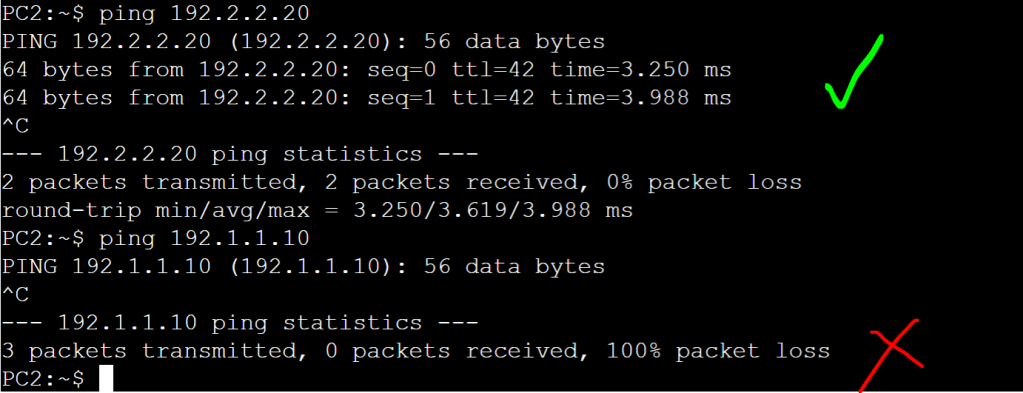
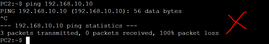
Everything looks good. We just did a simplified, manual version of macro-segmentation, DNAC style!
