1.2.f Route filtering with any routing protocol

I’m finally back to labbing after almost two years off. I’d like to say I have a good excuse, but I won’t bother. What’s important is that I’ve picked it up again. So let’s jump into it.

Filtering EIGRP Routes with Prefix-Lists

For this bit, we’ll filter routes coming in using prefix-lists. How hard can it be? We’ve got the following setup in EVE-NG:

Route 10.2.20.32/27 is currently being advertised from R2 into R1 with OSPF. The prefix list to be configured on R1 will need two lines. One to deny the 10.2.20.32/27 and one to permit everything else, since there’s an implicit deny at the end of prefix-lists.

conf t
ip prefix-list TEN_TWO deny 10.2.20.32/27
ip prefix-list TEN_TWO permit 0.0.0.0/0 le 32
router ospf 1
distribute-list prefix TEN_TWO in e0/2

It’s important to note that prefix-lists are more specific than access lists. If we configured an access list as deny 10.2.20.0 0.0.0.255, it would filter out anything starting with 10.2.20, including the 10.2.20.32/27 subnet. Prefix-lists are more specific. If our prefix-list said deny 10.2.20.0/24, it would NOT filter out the 10.2.20.32/27 subnet.

Another way to word it is the /nn says that number of bits must match exactly. For example, 128.0.0.0/2 would match anything that starts with bits 10xxxxxx.
Then the ge and le says what actual subnet to match. For example, 128.0.0.0/2 ge 16 le 16 would match all subnets from 128.0.0.0/16 through 191.255.0.0/16.

Limit Number of Received Routes in EIGRP

I was back and forth on where to include this knob, whether to put it here in route filtering, or do put it in the CoPP section. Well, it’s here. Using this setting, we can limit the number of received prefixes from a peer, and trigger warning messages once they hit a certain threshold. This is a per-neighbor config.

router eigrp E100
a ipv4 au 100
neighbor 10.1.1.2 maximum-prefix 6 50 warning-only

The above command limits it to 6 learned prefixes. So what does the 50 warning-only mean exactly? There are two different commands happening here after the maximum-prefix 6 part of the config.

  • The 50 means we want to generate a warning message once we hit 3 prefixes, e.g. 50% of our configured limit.
  • The warning-only command means we want to get a warning every single time our threshold of 6 is exceeded.

If we leave off the warning-only command, then EIGRP will tear down the adjacency once the maximum-prefixes are exceeded. One other thing to note, the default threshold is 80%. So if we leave the 50 off, we’ll get warnings once we pass that 80% mark.

Bonus: SD-WAN IOS Upgrade

This will be a quick post on upgrading an ASR IOS using SD-WAN. I’m going to go from 17.3.3 to 17.3.4a. We’ll just be uploading the image directly to vManage.

Add Image to Repository
  • In vManage, go to Maintenance > Software Repository > Software Images > Add New Software.
  • Select the first option, vManage.
vManage: Add Software Respository.
  • Click the Browse button.
  • Find your downloaded IOS file and click Open.
  • Click Upload.
vManage: Uploaded IOS 17.3.4a.
Upgrade Router IOS from vManage
  • In vManage, go to Maintenance > Software Upgrade > WAN Edge.
  • Select the router to upgrade and click Upgrade.
vManage: Select Router and Click Upgrade.
  • Select vManage, since that’s the repository we set up in the previous steps.
  • Select the IOS from the dropdown under Version.
  • Since this is a lab and we don’t need a Change Request we’ll check the box to Activate and Reboot.
  • Then click Upgrade.
vManage: Select IOS Version.

That’s it. Then we get send to the Task View where we can see things are going well.

vManage: Task View Shows the Progress.

1.5.a IBGP and EBGP peer relationships

Some trivia facts:

  • BGP runs on TCP port 179. The neighbor statement does the following:
    • Listen for remote address on TCP 179
    • Initiate a session to remote address on TCP 179.
    • If there’s a collision, the higher router-id becomes the TCP client. The lower router-id becomes the TCP server.
      • If the TCP server doesn’t expect the session it will refuse the connection.
        • You can see this in Wireshark:
          TCP 179 to the peer ->
          <- TCP reset from the peer [RST, ACK]
        • You can view this with:
          show control-plane host open-ports
      • The client packet is sourced from the outgoing interface in the routing table.
        • You can manipulate this with the update-source command.
  • BGP is a Path Vector protocol.
    • BGP sees the route as a path through a series of autonomous systems (AS), rather than as router hops.
    • The AS_PATH attribute is used to determine the best path based on fewest AS numbers.
  • If the AS is different between the two peers, then it’s eBGP. If they’re in the same AS, it’s iBGP.

Basic eBGP configuration:

R1:
router bgp 1
neighbor 1.1.12.2 remote-as 2
network 1.1.12.0 mask 255.255.255.0
network 10.1.1.1 mask 255.255.255.255

R2
router bgp 2
neighbor 1.1.12.1 remote-as 1
network 1.1.12.0 mask 255.255.255.0
network 10.1.1.2 mask 255.255.255.255

show ip bgp

Basic iBGP configuration:

R1:
router bgp 1
neighbor 1.1.12.2 remote-as 1

network 1.1.12.0 mask 255.255.255.0
network 10.1.1.1 mask 255.255.255.255

R2:
router bgp 1
neighbor 1.1.12.1 remote-as 1
network 1.1.12.0 mask 255.255.255.0
network 10.1.1.2 mask 255.255.255.255

show ip bgp

As shown above, the i shows it is internal.

BGP Sessions

  • After adding the neighbor IP and AS number, BGP attempts to open a session on TCP 179.
  • Routers verify the peer’s sender IP address against its own list of configured neighbors.
    • If a BGP session comes in from an unknown peer IP, BGP drops it and does not establish the connection.
  • The Router-ID is included with the session information.
    • If both routers are trying to set up the BGP session at the same time, the higher-router ID wins. The other session is dropped.
    • Router-ID is the numerically highest IP of any loopback, then interface that is up at the time of the start of the process.
    • You can (and should) manually enter the Router-ID.
    • The Router-ID is also used to ensure that the router doesn’t peer with itself.
  • In the show ip bgp summary command, IDLE means the session establishment is not currently happening.
  • Use debug commands to view the session states:
    • debug ip tcp transactions
    • debug ip bgp
    • debug ip bgp events
  • When the first attempts to open a session, it moves from IDLE to ACTIVE.
  • The session moves from IDLE to CONNECT once the communications swap with the neighbor.
  • CONNECT goes to OPENSENT while waiting for the neighbor to respond. The Open Message Contents are:
    • BGP Version Number
    • AS number of the local router
    • Hold Time (dead timer)
      • Routers agree on the lower value if the Hold Times aren’t the same.
      • Setting it to zero (0) means it never expires, keepalives are not sent.
    • BGP Router-ID
    • Optional parameters, such as session authentication.
  • When the local router receives an OPENSENT from the peer, the state goes to OPENCONFIRM, meaning the router sent a confirmation back to the peer.
  • Once everything checks out, the state goes from OPENCONFIRM to ESTABLISHED.

BGP Keepalives

They’re a 1:3 ratio. So 60 second keepalives with 180 seconds hold time (this is the default). If the peer relationship goes down, everything goes down. This means the whole process starts from scratch, the peering starts over, all routes must be learned again. This could be bad if there are a bazillion routes.

Why does BGP need a keep alive mechanism, you ask? Standard BGP communication is done with TCP, which doesn’t have any way of knowing if the neighbor is still there. And since BGP only sends updates when required it could potentially be very quiet for a long time.

The keep alive value isn’t sent, just the hold time. So keep alive must be determined by one of the following:

  • Locally configured keep alive.
  • Received hold time divided by 3.

So if I configure my keep alive for 10 seconds, but then I receive a hold time of 18 seconds, I’ll set the keep alive to 6 seconds.

1.4.e Optimization, convergence and scalability (OSPF)

1.4.e i Metrics

I already covered OSPF metrics in the previous post, so I’ll skip it here. I may come back and move things around later to make it easier to find stuff.

1.4.e ii LSA throttling, SPF tuning, fast hello
LSA Throttling (OSPFv2)

https://www.cisco.com/c/en/us/td/docs/ios-xml/ios/iproute_ospf/configuration/xe-16/iro-xe-16-book/iro-lsa-throt.html

LSA throttling does two things. Firstly, it’s gets us away from the 5-second rate-limit for LSAs, so we can get millisecond convergence. Second, it has a dynamic feature to slow things down when network instability is detected. The two commands are easy, but the timers and what each timer does can be a little confusing.

R1
router ospf 1
timers throttle lsa all [start interval] [hold interval] [max interval]

So what do these timers do?

  • Start Interval means how long do we wait before we send the second LSA of the same type. The first LSA is sent immediately, but since we’re not waiting 5 full seconds to send the second one, we need to know when to send that next one. We’ll set it to 200 milliseconds.
  • Hold Interval is the minimum time we’ll wait before sending two consecutive LSAs that are the same, meaning same Router ID, same LSA Type, and same LSA ID. Let’s set this to 500 milliseconds. The trick here is this time will keep doubling. So if our router’s links are unstable, the first LSA will go out immediately, the second one goes at 200 milliseconds (Start Interval), the third one goes out at the 700 millisecond mark (Start Interval + Hold Interval), the fourth one will go out at the 1700 millisecond mark (Start + Hold + (Hold x 2)
  • Max Interval is the longest we’re willing to wait before re-sending an LSA. We can set that to 2000 milliseconds. This means as our Hold Interval keeps doubling, at some point we want to make it stay at a max value.

Now we need to jump over to the neighbor router and tell it how often it should expect LSAs. This number needs to be equal to or less than the hold interval of the neighbor. This value basically says, “If you send me repeat LSAs faster than this time then I’m just going to drop them.” If R1 is sending LSAs every 500 milliseconds, but R2 isn’t willing to accept them any faster than 1 per second, then we’re wasting a lot of R1’s time and resources.

R2
router ospf 1
timers lsa arrival 500

SPF Throttling (OSPFv2)

https://www.cisco.com/c/en/us/td/docs/ios-xml/ios/iproute_ospf/configuration/xe-16/iro-xe-16-book/iro-short-path.html

SPF throttling is pretty similar to LSA throttling, except the start interval means “how long to wait before running the first SPF calculation.” The idea is if things are flapping, you just keep extending the hold-time until you reach the max-timer, then just running it only when that timer exceeds until things stabilize.

R1
router ospf 1
timers throttling spf 5 500 10000

LSA and SPF Throttling for OSPFv3:

Pretty much the same for v2 and v3, but v3 has its own dedicated config page.

https://www.cisco.com/c/en/us/td/docs/ios-xml/ios/iproute_ospf/configuration/xe-16/iro-xe-16-book/ip6-route-ospfv3-fastcon-xe.html

Bonus, non-blueprint item: LSA Flooding

If we recall, LSAs are grouped up and sent out every thirty minutes on a stable, converged network. But we can modify those timers as well.

R1:
router ospfv3 1
timers lsa arrival 1000 (same as v2)
timers pacing flood 100 (when to flood LSAs, in milliseconds)
timers pacing lsa-group 600 (this is seconds, it’s the interval at which we gather up our LSAs into a group, refresh them, checksum them, and age them.)

SPF Tuning

https://www.cisco.com/c/en/us/td/docs/ios-xml/ios/iproute_ospf/configuration/xe-16/iro-xe-16-book/iro-incre-spf.html

So what happens if we get a network change in our area, but we don’t want to do a whole big SPF recalculation? Isn’t there some way that we could just recalculate the bit that got change? Of course there is, it’s called Incremental SPF. Super easy config.

R1
router ospf 1
ispf

Fast Hello

Time for a commercial break. In honor of Fast Hellos, let’s enjoy Fast Goodbye.

Back to business. Here’s the reference link for Fast Hellos:
https://www.cisco.com/c/en/us/td/docs/ios-xml/ios/iproute_ospf/configuration/xe-16/iro-xe-16-book/iro-fast-hello.html

10 second hello packets? Are you kidding me? What year is this, 1987? Who has that kind of time!? Fast Hello basically means we can configure it to be less than 1 second. The concept is easy enough, but the configuration is a little counter-intuitive. You don’t actually set the Hello Timer. You just set the Dead Interval to 1 second, and set how many Hellos you want to send in that interval. The packets are actually sent with a hello timer of 0. Therefore, we can actually form a neighborship with different sub second timers, as long as the dead-interval matches at 1.

R1
interface gig 0/0
ip ospf dead-interval minimal hello-multiplier 4 (so we’re going to send a hello every quarter of a second.)

Verify it with show ip ospf interface gig 0/0.

1.4.e iii LSA propagation control (area types)

I covered this in the previous section, but one thing not called out on the blueprint is Virtual Links, so I’ll cover that here.

Virtual Links

To be an ABR, you have to have a link in AREA 0. That means Chainsaw, pictured above can’t be an ABR unless we set up a virtual link.

  • Virtual Links always exist in Area 0, meaning you can’t have a virtual link connecting area 20 to area 10. Your virtual link connects area 20 to area 0.
  • The routers that have the Virtual Link between them have to be in the same area. So we can’t have a Virtual Link between Dagger and Blowtorch.
  • You always use the router-id, not the interface IP address to create the Virtual Link. Since both routers are in the same area they know how to find each other by router-id.

Blowtorch
conf t
router ospf 1
router-id 0.0.0.2
area 10 virtual-link 0.0.0.3

Chainsaw
conf t
router ospf 1
router-id 0.0.0.3
area 10 vitual-link 0.0.0.2

Logically speaking, Chainsaw now has three different area connections, Gig0/0 in Area 10, Gig0/1 in Area 20, and a Virtual Link to Area 0.

1.4.e iv Stub router

I already covered these two topics in the previous section when I went on and on and on about Stub areas. I might move them under here later to make it easier to find them.

1.4.e v Loop-free alternate

Basically a backup-route. Sounds like someone is stealing ideas from EIGRP.

https://www.cisco.com/c/en/us/td/docs/ios-xml/ios/iproute_ospf/configuration/xe-3s/iro-xe-3s-book/iro-lfa-frr.html

First we’ll enable it and say we want all prefixes to have the same protection eligibility using the low keyword.

R1
router ospf 1
fast-reroute per-prefix enable prefix-priority low

Or we can decide which specific prefixes are high priority and only enable protection for them.

R1
ip prefix-list PL_OSPF_LFA seq 10 permit 192.168.150.0/24
route-map RM_OSPF_LFA permit 10
match ip address prefix-list PL_OSPF_LFA
router ospf 1
prefix-priority high route-map RM_OSPF_LFA
fast-reroute per-prefix enable prefix-priority high

1.4.e vi Prefix suppression

https://www.cisco.com/c/en/us/support/docs/ip/open-shortest-path-first-ospf/213404-open-shortest-path-first-prefix-suppress.html

The idea here is to save CPU cycles and save space in the routing table by suppressing the transit links within an area from showing up everywhere. There’s a link between R1 and R2, with prefix suppression we’re saying that R3 doesn’t need to know the details of that link. He only needs to know about the 10.1.1.0/24 host network that sits behind R1.

Honestly, I think the whole thing is dangerous and pointless in today’s networks. I want to be able to just directly ping R1 from R3 and see the routes in my routing table. But what do I know…

Globally:
R1
router ospf 1
prefix-suppression

Interface specific:
R1
interface gig 0/0
ip ospf prefix-suppression

1.4 OSPF (v2 and v3)

1.4.a Adjacencies

A quick review of everything we need to remember for adjacencies to form:

  • Unlike EIGRP, the hello timer and dead timer in OSPF must match. Remember the dead timer is 4x the hello timer, not the typical 3x. We’ll probably be tasked with tweaking these in the lab.
    • interface gig 0/0
      • ip ospf hello-interval 1
      • ip ospf dead-interval 3
  • You need a router ID. For the lab we’ll be sure to manually configure this and not rely on an interface, especially considering we could be talking about routers that are only running IPv6.
    • router ospf 1
      • router-id 0.0.0.1
  • The have to be in the same subnet.
  • Authentication has to match.
    • interface gig 0/0
      • ip ospf authentication message-digest
      • ip ospf authentication-key C!sco123
  • The area has to match.
    • router ospf 1
      • network 4.4.24.0 0.0.0.255 area 0
  • Hand in hand with the area matching, the stub flag has to match, too.
    • router ospf 1
      • area 1 stub
  • MTU has to match (by default, but this can be modified to be ignored.)
1.4.b Network types, area types

This seems like a good place for reviewing LSA types.

Type 1 – Router: There are two type 1 packets going around, one that shares the actual topology info, and one that validates point-to-point links. Why do we need to validate anything? R1 could be telling us about a route, but he could be a liar. Maybe he’s telling us about a loopback interface. But if R2 validates R1, then it’s more believable. R2 can say, “I vouch for R1, we’re connected on this link, he’s not lying.”
Type 2 – Network: These guys are sent from the DR and validate the other routers on that subnet. Similar to the secondary function of Type 1 LSAs, we need the DR to say, “I vouch for these knuckleheads, they’re with me,” referring to all the other routers on the DR’s segment.
Type 3 – Network Summary: This one comes from the ABR and summarizes the Type 1 and Type 2 LSAs to be sent to the neighboring area.
Type 4 – ASBR Summary: Also sent from the ABR, but it says, “Hey, I’ve got an ASBR here in my area. Here’s where you can find him.” So an ASBR Summary LSA only advertises a single /32 route, which tells other areas how to get to the ASBR.
Type 5 – AS External: OK, so Type 4 told us how to find the ASBR, but we still need the ASBR to tell us what he knows. That’s what Type 5 is used for, to tell the others about the redistributed routes learned from EIGRP, BGP, etc.
Type 7 – NSSA External: These are for our NSSAs. Since we can’t use Type 5 LSAs in the stub area, we need to disguise them as Type 7 LSAs. Then the ABR will make the switch to Type 5 LSAs when they leave the stub area.

Stub Areas
  • Stub Area: Our regular Stub Area just blocks external routes, plus it injects a default route (as an IA route). So anything that was redistributed from EIGRP, etc. So that’s LSA type 5 that we’re blocking. And since we’re not sending Type 5 LSAs into the area, we don’t need Type 4 LSAs either, so we’ll just block them both. The default route is advertised using Type 3 LSAs.
    • router ospf 1
      • area 5 stub
  • Totally Stubby: Totally Stubby is a subset of the Stub Area. It’s only applied on the ABR. The actual flag that determines if you’re able to make neighborships is the Stub Area flag. So Totally Stubby ABRs can neighbor with Stub Area routers. We’re going to block LSA type 5 (and 4) and (almost all) Type 3, and just inject the default route (so that’s just one IA route, but it is Type 3).
    • router ospf 1
      • area 5 stub no-summary
  • Not-so-Stubby-Area: We want to be a Stub area and block external routes, but we’ve got an ASBR in our area. We need to make sure those external routes are able to get to the rest of our network. The NSSA ASBR makes those external routes LSA type 7, N2 routes. So Type 5 is still blocked, but Type 7 gets through. So we’re still blocking any external routes coming from another area, we’re just letting our own external routes get out of our area. One thing to note, we’re not injecting a default route with an NSSA, so we’ll lose connectivity to outside external routes.
    • router ospf 1
      • area 10 nssa
  • NSSA Stub Area: This one is a subset of the NSSA flag. All the routers in the area are still set the NSSA flag. The only difference is you add default-information-originate to the ABR, since the NSSA doesn’t inject the default route. Now it’s an NSSA Stub area so it does everything an NSSA does plus everything a Stub Area does.
    • ABR Injects a default route.
    • ABR blocks external routes from being sent into the NSSA Stub area.
    • The internal ASBR that lives in the NSSA Stub area advertises his external routes as Type 7, N2 routes.
    • The ABR flips those Type 7 to Type 5 on the way out of the NSSA Stub area into Area 0 (he also changes the source router-id to himself so people know how to get to these E2 routes, since we don’t have a Type 4 LSA to tell us.)
    • router ospf 1
      • area 10 nssa default-information-originate
  • NSSA Totally Stubby Area: Same as an NSSA, we want do the whole LSA Type 7/Type 5 switcheroo, but we also want to block Type 3 LSAs.
    • router ospf 1
      • area 20 nssa no-summary
1.4.c Path preference
Path Cost

Within an area, OSPF path preference is figured by just adding up the cost of the links to get to a destination. Cisco routers use 10^8/BW to calculate cost. !0^8 is the reference bandwidth. You can change this default reference bandwidth with:

auto-cost reference-bandwidth

Of course, as we saw with EIGRP, this default sucks in today’s day and age because anything over 100M is a cost of 1. We can also modify the cost on any given link.

interface gig 0/0
ip ospf cost 10

But between areas OSPF basically becomes a distance vector protocol. When an ABR sends the Network Summary LSAs which sum up the routes in Area 5 to a router in Area 0, the Area 0 router doesn’t bother with any SPF algorithms, it just adds the cost that the ABR is advertising plus the cost to get the ABR.

For instance, R3 is an ABR and has the 10.1.1.0/24 network in Area 10. He uses a Summary LSA to tell the routers in Area 0, “Hey guys, to get to the 10.1.1.0/24 network, come through me, the cost is 50.” Then R4 who is in Area 0 says to himself, “Well I know the cost to get to R3 is 30, so the cost to 10.1.1.0/24 must be 80.”

Routing Tables

One more thing I don’t want to forget, OSPF has two types of routes, regular network routes that you can view with show ip route ospf, but there’s also an ABR/ASBR routing table. This one tells you how to get to the router-id of an ABR, ASBR, or ABR/ASBR. To view this table it’s show ip ospf border-routers. This table also tells us whether it’s inter-area or intra-area, and it shows the next hop and the interface to use.

External Routes

Why are there two types of External Routes (E1 and E2)?

  • E2 is the default and doesn’t bother with having a cost to get TO the ASBR, it’s only the cost that we configured during redistribution. The idea here is, “It doesn’t matter which path you take within our OSPF areas, what’s important is that you choose the ASBR that’s closest to the external route.” In other words, there’s no sense picking an ASBR that’s right next to us if that guy has to go around the world to get to the external network. We’re better off picking the ASBR that’s down the hall, since he’s got a really short path to the external network.”
  • E1 is the opposite. E1 includes the local cost + the external redistribution cost. The idea here is similar to BGP. “Just get the traffic out of our OSPF AS as fast as possible, once it’s out of our OSPF areas, I don’t care what happens to it.” So now we’re going to find the shortest path inside OSPF to an exit point (ASBR).

Path Type

If all other things are equal, OSPF uses path type as a tie breaker. Intra-Area is the most preferred.

  1. Intra-Area
  2. Inter-Area
  3. E1
  4. E2

If the path type is the same, and the cost is the same, OSPF will load-balance up to 16 equal-cost paths. So key point here, if R1 can get to 10.1.1.0/24 with a cost 100 in the same area, and can get to 10.1.1.0/24 with a cost of 100 through an ABR to area 2, it won’t load balance. They’re not equal even though they have the same cost. If the cost through the ABR is 99, then that will be that path that gets chosen.

Rule #1, Most Precise Route Always Wins

All these things are nice, but we can’t forget that a /32 will always win over a /24. A /24 will beat a /23. Other factors only matter if both networks are exactly the same. We won’t consider path types, or routing protocol administrative distance unless the networks are exactly the same.

1.4.d Operations
1.4.d.i General Operations

The basic config of OSPFv2 is covered above, so I’ll just jump to OSPFv3 here.

OSPFv3

There are some changes made to LSA types from v2 to v3 to make OSPF run more efficiently (e.g. subnet changes aren’t advertised with Router and Network LSA’s, which would trigger an unnecessary SPF calculation, and instead are advertised with Type 9 LSA.) But for this post, I’m just going to focus on the configuration.

One thing worth noting is they added an Instance ID. The idea behind this is that you can have 4 routers on the same network segment, but run two separate OSPFv3 instances so they won’t all try to become neighbors. With OSPFv2 you’d have to use different authentication keys to keep them separate, but then you’re stuck with endless “key mismatch” logs on each router as they refuse to give up trying to form that neighborship. The instance ID must match for a neighborship to form.

R1
router ospfv3 1
router-id 0.0.0.1
interface gig 0/0
ipv6 address 2001:db8:0:44::1/64
ipv6 ospf 1 area 0 [instance 0]

R2
router ospfv3 1
router-id 0.0.0.2
interface gig 0/0
ipv6 address 2001:db8:0:44::2/64
ipv6 ospf 1 area 0 [instance ]

Note, leaving the instance keyword off is the same as setting it to instance 0.

1.4.d ii Graceful shutdown

You can either shut OSPF down globally or per interface. The idea here is that the neighbors get notified right away so you don’t have to wait for them to time out before the re-run their SPF algorithm.

Globally:
router ospf 1
shutdown
router ospfv3 1
shutdown

Per Interface:
interface gig 0/0
ip ospf shutdown
ipv6 ospf shutdown

1.4.d iii GTSM (Generic TTL Security Mechanism)

The idea here is that OSPF sets outgoing TTL on OSPF packets to 255, then sets a minimum TTL value that you’re willing to accept. So if I know all of my OSPF routers are just two hops away from each other, then I can set the max hops to 2. That way any incoming OSPF packets I receive from 3 hops or more away (so that 3-hop TTL is 253, as direct neighbors are 255, two hops are 254, etc.), I’ll drop them. It’s a little confusing. At first I thought the hop-count would be the actual TTL that you’d accept, but it’s not.

Another example, if you set the hop-count value to 254, then you’re basically not using this security mechanism anymore. So when you want to enable it on R1, but you haven’t enabled it on R2, you can set R1’s hop-count to 254, then jump over and enable it TTL Security on R2, then come back and set R1’s hop count back to 5 or whatever you want it to be.

Globally
R1
router ospf 1
ttl-security all-interfaces hops 8

Per Interface
R1
interface gig 0/0
ip ospf ttl-security hops 8

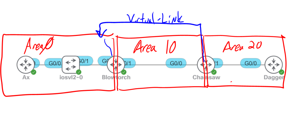
For IPv6 you can only configure TTL-Security for virtual-links and sham-links.

R1
router ospfv3 1
address-family ipv6
area 20 virtual-link 0.0.0.20 ttl-security hops 3
or
area 20 sham-link 2001:db8:10::A 2001:db8:20::D ttl-security hops 5

1.3.f v EIGRP stub with leak map

Stub Routers:
As we learned in 1.3.c iii, routes hang out in the active state waiting for a reply to the query they sent. What if we know for sure that the route we’re trying to learn about is definitely not down that alley behind that building over there. Do we really need to send queries down there and sit and wait for a response that we know is going to come back as, “Sorry boss, it’s a dead end.” No. We know it’s a dead end, so lets not send those queries.

R23:
router eigrp 100
eigrp stub

By default R23 will only send updates about connected and summary routes. But we can modify the stub command a little if we need more info from R23. If we want, we can set it for static or redistributed routes, as well.

R23:
router eigrp 100
eigrp stuf connected redistributed static summary

Note, there’s also a leak-map option, but that comes later in the blueprint. Then there’s the receive-only option, which means, “I’m not sending any routes to you. None…”

Default Route

If we want to include a default route, we have two options. We can redistribute a static route, or use a summary route. The summary route is probably a better idea because we can tweak the metrics on it.

R22
router eigrp R22
address-family ipv4 auto 10
af-interface gig0/2
summary-address 0.0.0.0/0

R23: show ip route

Let’s tweak that metric a bit.

R22
router eigrp R22
address-family ipv4 auto 10
topology base
summary-metric 0.0.0.0/0 1000000 10 255 0 1500

Leak Map

Since our stub router is only advertising connected and summary routes by default, we may want to tell it to also advertise network X. We’ll do that with a leak map.

R23
access-list 23 permit 23.1.1.1 0.0.0.0
route-map LEAKMAP
match ip address 23
router eigrp 10
eigrp stub leak-map LEAKMAP

1.3.f Optimization, convergence and scalability (EIGRP)

Optimization comes down to three things:

  • Failure detection: How fast can we figure out something’s wrong? (We should use BFD here, but let’s pretend we can’t because the task tells us not to.)
  • Information propagation: How fast can we tell our neighbors about the failure?
  • Fault repair: How fast can we calculate an alternate path?
1.3.f i Fast convergence requirements

For speeding up failure detection, we’ll just set the Hello Timers to really low numbers. (But even 3 seconds here is a lifetime compared to BFD’s 50 milliseconds.)

R20
router eigrp R20
address-family ipv4 autonomous-system 10
af-interface default
hello-interval 1
hold-time 3

1.3.f ii Query propagation boundaries

For improving information propagation we just need to make sure we have a good network design. Use summary addresses and stub areas to limit queries. Also, make sure there’s a feasible successor for every route so we can switch gears super fast (milliseconds) when the successor goes down. Without a FS, we’re at the mercy of the queries spidering out through the network and waiting for all the replies to come back.

1.3.f iii IP FRR (single hop)

Reference: https://www.cisco.com/c/en/us/td/docs/ios-xml/ios/iproute_eigrp/configuration/xe-17/ire-xe-17-book/ire-ipfrr.pdf

The loop-free alternate fast reroute is basically the FS. If a link goes down, the neighboring router has a backup path that it starts using without needing to do route calculations. The configuration is done in the named mode topology base section. Interestingly, the command doesn’t seem to be available on 15.8(3)M2 code that I’m labbing on. Looks like it was introduced with IOS-XE 3.7.

R22
router eigrp R22
address-family ipv4 auto 10
topology base
fast-reroute per-prefix all

Per-prefix is recommended, instead of per-interface. The alternative to the keyword all is to set a route-map for specific prefixes. For more granular control you can disable load-sharing and enable different tie-breaker rules to specify which path should be preferred if the primary link goes down. You assign each tie-breaker option with a priority, lower is better.

topology base
fast-reroute load-sharing disable
fast-reroute tiebreak lowest-backup-path-metric 1
fast-reroute tiebreak linecard-disjoint 2
fast-reroute tiebreak interface-disjoint 3
fast-reroute tiebreak srlg-disjoint 4

1.3.e EIGRP Named Mode

Updated 11/5/23 to include unicast vs multicast neighbors and the no next-hop-self command.
The nice thing about Named Mode is everything is (sort of) in the same place, instead of some config being under router eigrp and some config being under individual interface configs. Is that it, it’s just more organized? There are also these advantages:

  • IPv6 support.
  • VRF support.
  • Wide Metrics (discussed in a previous post) to support links bigger than 2Gig.
  • Configurations are centralized, instead of some being under the router eigrp section, and some being under the interface config.

Let’s break named mode down into three sections.

  • address-family: Network commands, neighbor commands (for unicast neighbors).
  • address-family-interface: These commands used to live under individual interfaces and usually only affect one neighbor. This includes things like authentication, summary-addresses, passive-interface, and hello timers.
  • address-family topology: This is where we do our redistribution, distribute-lists, and variance commands.

For the sake of having fun, let’s reconfigure R20 that we did for the summary-route and leak map section, but this time we’ll set a bunch of weird metrics for the summary route.

R20
router eigrp R20
address-family ipv4 autonomous-system 10
af-interface default
passive-interface
af-interface gig0/0
no passive-interface
summary-address 10.10.104.0/22 leak-map LEAKMAP
af-interface gig 0/1
no passive-interface
summary-address 10.10.104.0/22
exit
topology base
summary-metric 10.10.104.0/22 999999 479 249 29 1399 distance 169

variance 2
exit
network 5.5.10.0 0.0.0.255
network 5.5.80.0 0.0.0.255
network 10.10.104.0 0.0.0.255
network 10.10.105.0 0.0.0.255
network 10.10.106.0 0.0.0.255
network 10.10.107.0 0.0.0.255

We can view these modified metrics on the neighbor R21.

R21: show ip eigrp topology 10.10.104.0/22

Compared with the direct route learned because of our leak-map.

R21: show ip eigrp topology 10.10.105.0/24
1.2.e VRF-aware routing with any routing protocol

VRF config for EIGRP is done under named mode. It’s pretty straightforward.

R17
vrf definition 1
address-family ipv4 unicast
vrf definition 2
address-family ipv4 unicast

interface gig 0/0
vrf forwarding 1
ip add 5.5.78.17 255.255.255.0
interface gig 0/1
vrf forwarding 2
ip add 5.5.27.17 255.255.255.0
(obviously we’d need at least two interfaces or subinterfaces in each VRF, or we’re a bit of a dead end. But for the sake of brevity, I’m just showing one here.)

router eigrp R17
address-family ipv4 vrf 1 auto 10
network 5.5.78.0 0.0.0.255
address-family ipv4 vrf 2 auto 10
network 5.5.27.0 0.0.0.255

Notice we’re using the same AS for both VRFs. There’s no rule saying we can’t. And to test it we can do a traceroute from one interface to the other interface on the same router.

R17: traceroute
Unicast Neighbors vs Multicast Neighbors

With traditional EIGRP config, neighborships were formed using multicast on 224.0.0.10. With named mode you have the option of setting up unicast neighbors. This is a per-interface config, so you can have one neighbor using multicast on Gig0/1, and other neighbors still using multicast on Gig0/2 and Gig0/3. One thing to note, when you enable a unicast neighbor, that interface no longer accepts 224.0.0.10 EIGRP multicast packets. So the neighborship goes down until you configure both sides.

router eigrp E100
address-family ipv4 autonomous-system 100
neighbor 10.1.1.2 Gig 1

No Next-Hop-Self

This one is weird enough to show up on the lab exam. On the following diagram, all three routers’ Gig1 interfaces are in the same subnet, 10.1.1.0/24. R1 and R2 are EIGRP neighbors. R2 and R3 are OSPF neighbors. R2 is redistributing OSPF into EIGRP.

The result is when R1 tries to ping 300.3.3.3, the traffic flows to R2 first, then to R3, then directly back to R1. A more optimal path would be if R1 and R3 communicated directly. This is where no next-hop-self comes into play. Turning off next-hop-self prevents R2 from setting itself as the next hop for EIGRP routes it is advertising. This assumes that if they’re in the same subnet, they can reach each other.

R2
router eigrp E100
add ipv4 au 100
topology base
redistribute ospf 1 metric 100 1 255 1 1500
af-interface Gig1
no next-hop-self

1.3.d EIGRP load balancing

1.3.d i Equal-cost

Enabled by default, as long as the metrics match. Nothing really to do here.

1.3.d ii Unequal-cost

Use the variance command. The only trick is when you multiply your best path’s metric by the configured variance, the product has to be higher than any potential path’s metrics, otherwise they still won’t be considered. For example, if you have two paths, one with a metric of 200,000 and one with a metric of 500,000 and you set the variance to 2, it wouldn’t trigger unequal cost load-balancing. A variance of 2 would only trigger load-balancing for metrics of 400,000 or less. So we’d have to set the variance to 3.

R17
router eigrp 10
variance 3

1.3.d iii Add-path

Reference: https://www.cisco.com/c/en/us/td/docs/ios-xml/ios/iproute_eigrp/configuration/xe-17/ire-xe-17-book/ire-add-path.pdf

The sequence of this blueprint topic is a little wonky, since Add-path if for DMVPN’s, which haven’t been covered yet, and it requires EIGRP Named-mode, which hasn’t been covered yet.

So what’s the deal with Add-path? We’ve come to expect equal cost load balancing by default with EIGRP. However, with EIGRP over DMVPN, you only get one path advertised. Add-path is a feature to advertise up to four paths to the same destination across the DMVPN. A couple notes about it:

  • You have to use named mode.
  • You can’t use the variance command.
  • You configure it on the DMVPN hubs under the af-interface tunnel settings.
  • You have to disable eigrp next-hop-self on those tunnel interfaces.
    • We want EIGRP to tell us the peer IP address to get to the next-hop, not tell us “use interface Tunnel 10”.
    • We need the no-ecmp-mode command because no next-hop-self by itself only evaluates the first entry in the topology table for that route. Using no-ecmp-mode will tell it to apply no next-hop-self to subsequent entries, as well.

R21
router eigrp DMVPN
address-family ipv4 autonomous-system 10
af-interface tunnel 10
no next-hop-self no-ecmp-mode
add-paths 4