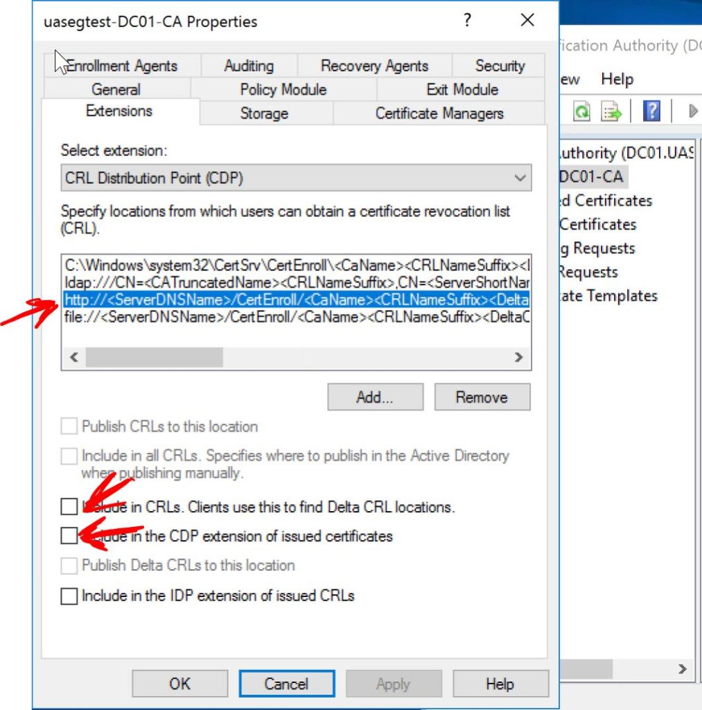
Summarization is per interface. So let’s only summarize towards R18 (G0/1) and see what happens.
interface g0/1 ip summary-address eigrp 10 10.10.104.0/22
So now R21 gets the individual routes and R18 only gets the summary. That means the preferred path from R17 will be through R21, since it’s the longer mask of /24. Let’s get things back to a level playing field by also summarizing on G0/0.
interface gig 0/0 ip summary-address eigrp 10 10.10.104.0/22
Now the path from R17 will prefer the shorter metric and take R18. But maybe we want most of the traffic going that way, but we want traffic from R17 to 10.10.105.0 to go the longer way through R21. For that we can use a leak-map.
access-list 5 permit 10.10.105.0 0.0.0.255 route-map LEAKMAP match ip address 5 interface gig 0/0 ip summary-address eigrp 10 10.10.104.0/22 leak-map LEAKMAP
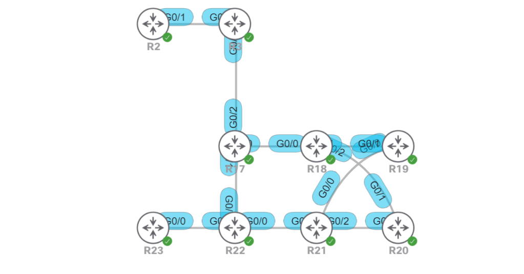
We can verify it with a show ip route from R21.
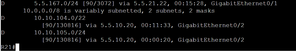
R21: show ip route
And on R17, we prove that even though the path through R22 has a higher metric, it doesn’t matter because it is a more precise route. Metrics only count when the routes are exactly the same.
Let’s just burn through a list of commands we need to memorize:
Basic Config: router eigrp 100 network 10.1.1.0 0.0.0.255 ! Disabling auto-summarization isn’t required anymore, it’s the default. no auto-summary
1.2.i Routing protocol authentication
Authentication with EIGRP is just MD5 in classic mode. Named Mode lets you do MD5 or SHA-256. Let’s set up the keychain first.
key chain KEY_EIGRP key 1 key-string C!sco123
Classic EIGRP interface gig 0/0 ip authentication mode eigrp 10 md5 ip authentication key-chain eigrp 10 KEY_EIGRP
Named Mode router eigrp R17 address-family ipv4 vrf 1 auto 10 af-interface gig 0/0 authentication mode md5 authentication key-chain KEY_EIGRP
Stub Routers: As we’ll learn in 1.3.c iii, routes hang out in the active state waiting for a reply to the query they sent. What if we know for sure that the route we’re trying to learn about is definitely not down that alley behind that building over there. Do we really need to send queries down there and sit and wait for a response that we know is going to come back as, “Sorry boss, it’s a dead end.” No. We know it’s a dead end, so lets not send those queries.
R23: router eigrp 100 eigrp stub
By default R23 will only send updates about connected and summary routes. But we can modify the stub command a little if we need more info from R23. If we want, we can set it for static or redistributed routes, as well.
Note, there’s also a leak-map option, but that comes later in the blueprint. Then there’s the receive-only option, which means, “I’m not sending any routes to you. None…”
1.3.c i General operations
Let’s use this section to screw up our metrics and timers. We’ll start with the metric weights which are the K values that we should really never touch. Default is 1 0 1 0 0. Note the first 0 is the TOS, which says we can put a value of 0-8, but only 0 is allowed.
Now that we modified the metrics, we can’t have any EIGRP neighborships unless they all modify their metrics, too. What a mess.
Timers: interface gig 0/1 ip hello-interval eigrp 1 ip hold-time eigrp 3
Default timers are 5 and 15. We set them to 1 second hello interval and 3 second wait time to receive a hello. Note that if we didn’t change the peer to send faster than 5 seconds, then our 3 second timeout will kill the neighborship.
1.3.c ii Topology table
What’s there to say here besides show ip eigrp topology? The received routes get funneled down into the topology table (if they qualify per our FC), from there the best routes get chosen and sent to our routing table.
1.3.c iii Packet types
Just a couple packet types, and two of them are really just the same packet.
Hello/Ack: Hellos are multicast and unreliable. If it’s empty hello, it’s an Ack. Acks are always unicast, but still unreliable.
Updates: Updates use reliable delivery and contain… routing updates, of all things. They can be multicast or unicast. If I decide to send them because I had a topology or metric change, then I’ll multicast them. But if my peer is requesting an update, I’ll just unicast it.
Queries/Replies: If we get an input event, we know something in the network has changed and we have to do our DUAL calculations again. This is where routes go from passive (normal state) to active (querying and waiting for replies). Some of the things that trigger this are:
Directly connected link goes up or down, or the cost changes.
We receive an update, query, or reply.
Requests: These aren’t actually used. Forget about them.
SIA-query/SIA-reply: We’ll talk about these in the next section.
1.3.c iv Stuck In Active
SIA is when our route is hanging out waiting for replies from ALL neighbors that we sent queries to, and those neighbors are all hanging out waiting for replies from all the neighbors that they sent queries too, and on and on. Stuck-in-Active is bad because it causes the router that’s waiting for the reply to just say, “Oh well, I guess he’s dead, blow away those routes.” Then we start over with a new neighborship, and that cycle can repeat. That’s why they made the SIA-retransmit timer and the SIA-query and SIA-reply.
SIA-retransmit timer: This is set to half of the active timer (so 90 seconds). When it expires, we send an SIA-query.
SIA-query/SIA-reply: These basically say, “Hey man, I’m still waiting on a reply from my query.” and the neighbor sends an SIA-reply that says, “Hang tight, duder. I’m working on it. Don’t blow me away yet, though, I’m still here.” This causes the regular query timer to reset so the neighbor has more time to get his act together.
1.3.c v Graceful shutdown
There’s not really anything to configure here. Graceful Shutdown is a mechanism where a router can notify a neighbor that says, “Hey, my EIGRP is going down, so don’t waste your time trying to figure out if I’m still alive or not.” You can trigger graceful shutdown a couple ways.
reload
no router eigrp
no network [peer subnet]
clear ip eigrp neighbor
Effectively what the router does is send a Hello message to the peer with the K values all set to 255. The peer recognizes this as code-word for graceful shutdown.
I’m going to burn through these topics pretty quick and just touch on unique scenarios. EIGRP has been around forever and there are a million resources that cover it. So for adjacencies, I’m just going to make up a task that will challenge our knowledge of unicast vs. multicast neighbor relationships.
EIGRP Topology, Task#1
Task#1: R1 and R5 must share EIGRP routes. Multicast is not allowed.
Let’s assume that the firewall between R1 and R5 is blocking multicast traffic for 224.0.0.10. That means we need to set up a unicast neighborship.
R1 conf t router eigrp 100 neighbor 192.0.0.18 Gig0/3
R5 conf t router eigrp 100 neighbor 192.0.0.17 gig0/0
Let’s verify it.
R1: Unicast neighbor.
1.3.b Best path selection
A quick reminder, EIGRP AD is 90, routes redistributed into EIGRP have AD 170.
The metric calculation is simply bandwidth + delay. But what about this 256 business? I thought it was something like metric = 256 ((10^7/bandwidth) + (delay/10)). OK, fine, so it’s a tiny bit more complicated than bandwidth + delay.
Bandwidth = [ten million / (the lowest bandwidth along the path, based on what’s configured on the outgoing interfaces)] * 256 OR (10^7/BW)*256
Delay = [the sum of all the delays as configured on outgoing interfaces along the path / 10] * 256
Why are we dividing delay by 10? Because EIGRP counts delay in 10’s of microseconds. The interfaces are in actual microseconds. So we have to divide by 10. Nothing’s ever easy.
1.3.b i RD, FD, FC, successor, feasible successor
We should know all this stuff by heart from CCNA and CCNP exams. But I’ll regurgitate it here to help keep me sharp on it.
RD: Reported Distance (used to be Advertised Distance, but it was too confusing with Administrative Distance). It’s what our neighbor tells us through routing updates what the metric is to get to route X.
FD: Feasible Distance is what I figured out the shortest distance is to route X. It’s the reported distance, plus the cost to get me to the neighbor that told me their reported distance.
FC: Feasibility Condition. I couldn’t remember this one and had to look it up. Good thing I didn’t skip through this section. It’s an easy one, though. This is what you use to determine whether or not you want to keep track of any halfway decent backup routes in your topology table. We might learn a bunch of paths to route X, but we only want to keep them handy if they meet the FC, meaning the Reported Distance that R3 told us is LESS THAN the Feasible Distance by going through R2.
To put it another way, R2 told us we can ride their bus for $100 to get to destination X. R3 can get us there for $120. But I know it’s going to cost me $30 to get to R2’s bus station, for a total cost of $130. So I’m definitely going to take R2’s bus. But I’m going to keep the info for R3 handy, just in case I need it. However, if R3 told us they’d charge $200 to get to destination X, I wouldn’t even consider it, I’d just tear up their estimate and throw it in the trash.
S
Successor: That’s just the next hop.
Feasible Successor: This would be R3 in our scenario above. It’s not in our routing table, but we’re hanging onto the info in our EIGRP topology table, just in case we need it.
1.3.b ii Classic Metrics and Wide Metrics
The Classic metric is just the standard formula. But let’s talk specifically the (10^7/BW) part. The breaks down as follows for different link speeds:
Gigabit: 10,000,000 / 1,000,000 = 10. So our composite metric is (10 + delay) * 256. Makes sense so far.
10 Gig: 10,000,000 / 10,000,000 = 1. Composite metric is (1 + delay) * 256. OK, so now the danger is becoming apparent.
11 Gig: 10,000,000 / 11,000,000 = 0 (rounded down to zero). Composite metric is (0 + delay) * 256. The problem becomes really obvious with 11Gig links, but we can see a problem even sooner. Let’s verify that by checking 3Gig, 4Gig, and 5Gig bandwidth.
R3: bandwidth modified
Hence the need to introduce Wide Metrics. The solution is to just multiply our classic 10^7 by 65535. So link speeds can scale up to 655 terabits/second.
Delay is also modified. Instead of 10^-6, it becomes 10^-12 (picoseconds).
One more thing, a new K value was added, value K6. It’s set to 0 by default (same as K2, K4, and K5). The idea is it could be used for jitter or some other future use.
So which metric are we using? It’s easy, if we’re in classic EIGRP we’re using the classic metric, if we’re in named-mode EIGRP, we’re using the wide metric. We can do an easy check with show ip protocols. If we see a K6 value listed, we know we’re in wide metric.
The process flow is: 1. The routing protocol, OSPF for instance, discovers a neighbor. 2. The routing protocol tells the BFD process to start a BFD peering relationship with that same neighbor. 3. If a failure occurs, BFD tells the routing protocol process that the link failed. 4. The routing protocol process tears down the neighborship right away.
Judging by the sequence, we should be able to figure out that the BFD config will live underneath each respective routing protocol config section. So it makes sense to break this out into routing protocol sections. There are a couple factoids worth calling out:
If we’re running BFD in echo mode we need to disable icmp redirects to avoid high CPU utilization.
no ip icmp redirects
BFD is mostly data plane, so it’s you don’t have CPU overhead that you get with super-low timers on routing protocols.
A single BFD process can notify multiple routing protocols. For instance, if you have OSPF and EIGRP running on the same link, you just need one BFD process.
The configuration is pretty easy. There are two options, enable it with the bfd interval command on each interface, or create a template and apply the template to each interface. We’ll do both methods, a template on R3 and manual on R4. We’ll set to the minimum transmit and receive to 100 milliseconds each, and set it to three strikes and you’re out. That should give use a total of 300 millisecond failure detection.
R3 conf t bfd-template single-hop BFD_1 interval min-tx 100 min-rx 100 multiplier 3 !But wait, since we’re using 100 milliseconds for both, let’s use the both keyword instead. interval both 100 multiplier 3 interface gig 0/0 bfd template BFD_1
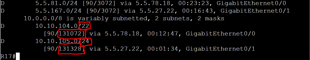
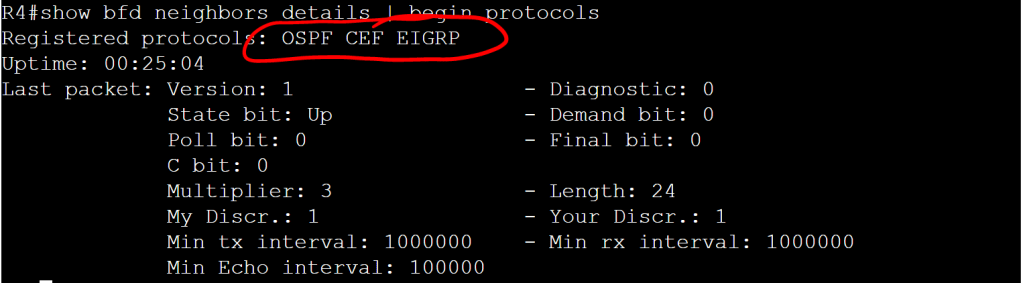
Pretty simple, but we don’t have bfd echo enabled. We can verify that with show bfd neighbors details.
R3: show bfd neighbors details
It’s important to note that it’s the neighbor that doesn’t have echo enabled. Let’s enable it on both sides.
R3 conf t bfd-template single-hop BFD_1 echo
R4 conf t interface gig 0/0 bfd echo
This change highlights the benefits of templates. If we’re doing the config on 10 interfaces, we’ll need to go into each interface and add the bfd echo command. But if we are using a template, we just update the template, and it applies to all interfaces where that template is in use.
OK, so we have our BFD neighborship up, but at this point it’s not actually doing anything for us because we didn’t tie it in to any routing protocols. So let’s do that real quick, super easy, one command.
OSPF
OSPF tells BFD to start once the neighborship transitions to FULL.
OSPF will only set up BFD peering session with the DR and the BDR on a network link.
R3 and R4 conf t router ospf 1 bfd all-interfaces
EIGRP
The EIGRP config for BFD is almost identical to OSPF.
R3 and R4 conf t router eigrp 100 bfd all-interfaces
Let’s check it out with the show bfd neighbors details command.
R4: show bfd neighbors details
BGP
The config for BGP is a tiny bit different. It’s set with the neighbor x.x.x.x fall-over bfd command. And yes, that says fall-over and not fail-over. As in “fall-over drunk”. I would think it should be fail-over, but what the hell do I know.
Even though IS-IS isn’t listed as a protocol we need to know for the Ent. Inf. exam, it is a core component of SDA, so we’re definitely going to come up against it at some point. The good thing is the BFD config is pretty similar to OSPF and EIGRP. It’s just the all-interfaces command under the router process.
R3 conf t interface gig 0/1 ip router isis router isis net 49.0000.0000.0003.00 bfd all-interfaces
R4 conf t interface gig 0/0 ip router isis router isis net 49.0000.0000.0004.00 bfd-all interfaces
HSRP
The cool thing about HSRP is that BFD is enabled by default, you don’t need the specific standy bfd or standy bfd all-interfaces commands. You just need the regular per-interface bfd command.
This whole chunk of the blueprint doesn’t really make sense because it’s mostly topics that will be covered under individual routing protocols. The only subsections I’m going to cover under 1.2 are 1.2b. VRF-Lite (covered in a separate post), Policy Based Routing (PBR, which I’ll cover below), and Bidirectional Forwarding Detection (BFD, which I’ll cover in the next post). Everything else will be covered as part of EIGRP, OSPF, and BGP.
1.2.c Static Routing
OK, I lied. One quick word about Static Routing. The legend has always been (at least according to CBT Nuggets) that the rules of the lab explicitly say that static routing isn’t allowed. But I think Floating Static Routes are worth mentioning here. Also, there’s an entire chapter (Chapter 3) of Routing TCP/IP, Volume 1, 2/e (Carroll, Doyle) dedicated to static routing that’s a pretty good read.
Configuring a floating static route is pretty simple, you just set the administrative distance (AD) at the end of the line to something higher than your routing protocol AD.
R1 conf t ip route 192.1.1.0 0.0.0.255 192.0.0.6 111
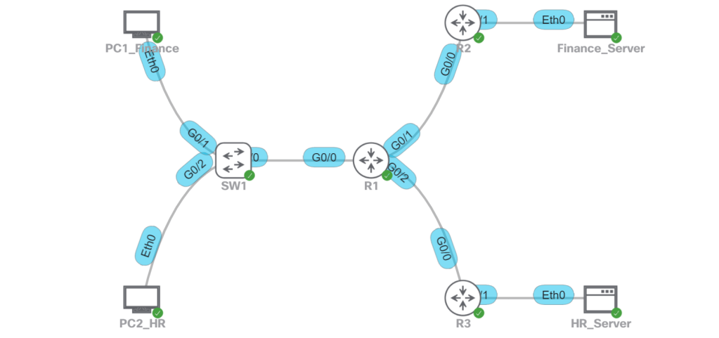
PBR with route-maps is basically the If/Then statements of routing. The topology is pretty similar to the one from the previous post about VRF-lite, with some minor changes.
PBR Topology
The idea is that R1 is currently taking the shortest path to the Finance_Server and the HR_Server, through R2. OSPF is running on all of the routers and on SW1. SW2 is just L2. The task that we want to accomplish with PBR is to have the HR traffic go across R3 and R4 to the HR_Server. All other traffic will go through R2, which includes Finance user traffic to Finance_Server or HR_Server, as well as HR user traffic to the Finance_Server. For the purposes of this lab, we’re not doing any type of segmentation. Anybody can talk to anybody.
For reference material, I’m still using Routing TCP/IP, Volume 1, 2/e, specifically Chapter 14: Route Maps. Here’s a great quote from that chapter, “Policy routes are nothing more than sophisticated static routes.”
Match IP Address
The interesting thing with PBR route maps, when you type match ? you get about 20 options. But the only ones used for PBR are match ip address [ACL] and match length <0-2147483647>. We’ll probably match on IPs 99% of the time, so we’ll look at that first.
The config is pretty straightforward, it’s just three steps: 1. Define the ACLs. 2. Create the route-map. 3. Apply the route-map to the interfaces.
R1 conf t ! This first one could have just been a standard ACL. access-list 110 permit ip 192.168.10.0 0.0.0.255 any !This second one is only for the HR subnet talking to the HR server. access-list 120 permit ip 192.168.20.0 0.0.0.255 host 192.2.2.20
!Create the route-map. route-map RM_PBR permit 10 match ip address 110 set ip next-hop 192.0.0.2 route-map RM_PBR permit 20 match ip address 120 set ip next-hop 192.0.0.6
!Apply it to the interface(s). interface gig 0/0.10 ip policy route-map RM_PBR interface gig 0/0.20 ip policy route-map RM_PBR
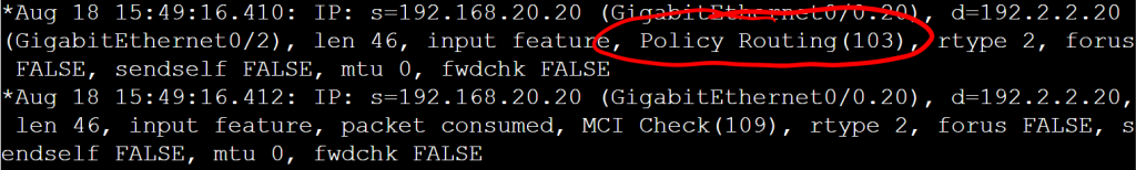
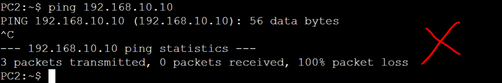
That’s it. Pretty simple config. Let’s verify with a traceroute from the HR PC.
PC2 traceroute.R1: debup ip packets 120.
Match Length
Another interesting thing mentioned in the Routing TCP/IP book is segregating small packets (telnet) from big packets (ftp) using the match length option. I feel like it’s an obscure enough knob to turn that it could definitely show up on the lab.
R1: conf t route-map RM_length !Match a minimum of 1000 octets and maximum of 1600 octets. match length 1000 1600 set ip next-hop 192.0.0.6
Local Policy
So far this has all been policy applied to an ingress interface. What about local traffic originating from the router? We can apply a route-map using a global config command, ip local policy route-map RM_length. One thing to avoid would be accidentally applying policy to control plane traffic, routing updates for instance, which prevent the hellos from going out the correct interfaces. We can avoid this with a match statement that matches on the local IP of the router, but no set statement, which means “just route normally.” For instance:
R1 conf t !ACL that defines the local ip addresses. access-list 1 permit host 192.0.0.1 access-list 1 permit host 192.0.0.5 access-list 1 permit host 192.0.0.9 access-list 1 permit host 192.0.0.13
!Define the route map and tell it to ignore anything originating from those 4 local IPs, just route them normally. route-map RM_length 10 match ip address 1 route-map RM_length 20 match length 0 400 set ip next-hop 192.0.0.6
!Then apply the route map with the local policy. ip local policy route-map RM_length
PBR QoS
We’re going to hit up QoS in section 4 of the CCIE blueprint.
This is a pretty important topic when we get to the DNAC section, so we may as well get it out of the way. For background trivia, the “lite” part means that we’re VRFs without MPLS label imposition or without MP-BGP extensions. And it’s fewer calories.
References: MPLS and VPN Architectures, Volume II (Cisco Press)
Note: Regarding naming the VRFs, I’ve typically used a descriptive name which is what is usually used in example configs, such as “CAMPUS” and “LAB”. But then I started naming them to match the Virtual Network names in DNAC, which makes sense for readability and mapping to the corresponding VLANS. However, after messing with SD-WAN, they just slap a number on there and I’ve found that to be super easy to work with when doing pings, etc. So I’m going to stick with numbers for now and hopefully they’ll be logically mapped later to DNAC VNs without being too confusing.
The idea for this setup is that we don’t want Finance users talking to the HR server, and we don’t want HR users talking to the Finance server. A good way to do this in a real life scenario would be with CTS tags, which would be assigned to the users when the log ont the network with 802.1x, and then enforced at the destination point where the IPs of those servers have a static IP to SGT mapping (micro-segmentation). But since we’re labbing VRFs, we’re going to do this with macro-segmentation (VLAN + VRF).
Lab Topology
Finance
VLAN 10
192.168.10.0/24
VRF 10
Finance_Server: 192.1.1.10
HR
VLAN 20
192.168.20.0/24
VRF 20
HR_Server: 192.2.2.20
R1: config t ! It’s good practice to have at least one ip in the global routing table. ! In case there’s a service that needs it, like BGP that needs it to auto-assign a router-id. interface Loopback0 ip address 192.168.254.1 255.255.255.255
! Configure the WAN side interfaces. interface gig0/1 vrf forwarding 10 ip address 192.0.0.1 255.255.255.252 interface gig 0/2 vrf forwarding 20 ip address 192.0.0.2 255.255.255.252
! Configure the LAN side sub-interfaces. interface gig 0/0.10 vrf forwarding 10 encapsulation dot1q 10 ip address 192.168.10.1 255.255.255.0 interface gig 0/0.20 vrf forwarding 20 encapsulation dot1q 20 ip address 192.168.20.1 255.255.255.0
! Last bit, we’ll configure OSPF. For simplicity, we’ll match the OSPF process number to the VRF. router ospf 10 vrf 10 network 192.0.0.0 0.0.0.3 area 0 network 192.168.10.0 0.0.0.255 area 0 router ospf 20 vrf 20 network 192.0.0.4 0.0.03 area 0 network 192.168.20.0 0.0.0.255 area 0
That works fine for a simple setup with a layer 2 trunk link between SW1 and R1. But what if we want all layer 3 links everywhere so we don’t have any STP in our network? Let’s setup SW1 with VRFs and we’ll map those VRFs to the corresponding VRFs on R1. That way, we can totally segment traffic across the entire path.
Point-to-Point Links will use 192.0.0.x/30 IP addresses.
Modify the ip config on R1 sub-interfaces.
Configure SVI interfaces (10 and 20) on SW1 with P2P IP addresses.
Make some VLAN modifications on SW1.
VLAN 10 will become VLAN 110.
VLAN 20 will become VLAN 120.
SVIs 110 and 120 will be configured as the gateway IPs for PC1 and PC2.
OSPF will be configured on SW1 and R1.
There will be no routing permitted between PC1 and PC2.
R1: ! Change the IP on gig0/0.10 and gig0/0.20 interface gig 0/0.10 vrf forwarding 10 encapsulation dot1q 10 ip address 192.0.0.9 255.255.255.252 interface gig 0/0.20 vrf forwarding 20 encapsulation dot1q 20 ip address 192.0.0.13 255.255.255.252
! Modify the OSPF config router ospf 10 vrf 10 no network 192.168.10.0 0.0.0.255 area 0 network 192.0.0.8 0.0.0.3 area 0 router ospf 20 vrf 20 no network 192.168.20.0 0.0.0.255 area 0 network 192.0.0.12 0.0.0.3 area 0
SW2: config t ! Create the VRFs. vrf definition 10 address-family ipv4 vrf definition 20 address-family ipv4
! Create the SVIs. interface vlan 10 vrf forwarding 10 ip address 192.0.0.10 255.255.255.252 interface vlan 20 vrf forwarding 20 ip address 192.0.0.14 255.255.255.252
! Configure the VLANs and SVIs for LAN access. vlan 110 name FINANCE interface vlan 110 vrf forwarding 10 ip address 192.168.10.1 255.255.255.0 interface gig 0/1 switchport access vlan 110
! Configure OSPF on SW1. ! Note, moving all these IPs around in the lab and not explicitly defining OSPF router-ids resulted in duplicate router-id errors on both R1 and SW1. So I explicitly defined them and then did a clear ip ospf process, which cleared it up. router ospf 10 vrf 10 network 192.0.0.8 0.0.0.3 area 0 network 192.168.10.0 0.0.0.255 area 0 router ospf 20 vrf 20 network 192.0.0.12 0.0.0.3 area 0 network 192.168.20.0 0.0.0.255 area 0
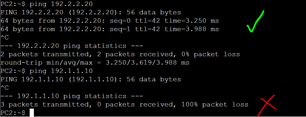
Now let’s just verify connectivity:
PC 1 (Finance) can ping the Finance server, but not the HR server.PC2 (HR) can only ping the HR server, not the Finance server.PC2 cannot ping PC1.
Everything looks good. We just did a simplified, manual version of macro-segmentation, DNAC style!
I’m going to focus on two specific use tasks with EtherChannel.
Two trunk ports on a switch connecting to two ports on a router, which will be configured as sub-interfaces.
Enable TrustSec on those ports. This will come into play when we get to the Border/Control Plane node on SDA and we want to connect it to the WAN Edge router (possibly our SD-WAN Edge).
1.1.d i LACP, static
Notice there’s no PAGP on the list, since it’s not supported on most devices anymore. Just one less thing to worry about. For starters we’ll just work with SW2 and R26.
The only real trick to it is the flow is a little different on the router vs the switch.
R26 conf t !We have to define the port channel interface first. interface port-channel 1 !And enable TrustSec on the port channel. Unlike the switch, you only apply it to port-channel config. It won’t take the cts commands on the individual channel-group members. cts manual policy static sgt 2 trusted exit !Now we can add our interfaces gig 0/0/4 and gig 0/0/5 to the channel-group. interface range gig 0/0/4-5 channel-group 1 mode active exit !And since we’re laying the groundwork for SDA, let’s add the VRFs. vrf definition 1024 rd 1:1024 vrf definition 1025 rd 1:1025 vrf definition 1026 rd 1:1026 !Last bit, we’ll create the sub-interfaces under the port-channel. The tricky part, we have to enable cts manual on all sub-interfaces. interface port-channel 1.1024 encapsulation dot1q 1024 vrf forwarding 1024 ip add 4.14.24.1 255.255.255.0 cts manual policy static sgt 2 trusted !Rinse and repeat for each sub-interface. interface port-channel 1.1025 encapsulation dot1q 1025 vrf forwarding 1025 ip address 4.14.25.1 255.255.255.0 cts manual policy static sgt 2 trusted !1026 interface port-channel 1.1026 encapsulation dot1q 1026 vrf forwarding 1026 ip address 4.14.26.1 255.255.255.0 cts manual policy static sgt 2 trusted
It’s good practice to shut down these interfaces when applying the TrustSec config. Another thing I’ve seen on some older ASR code is that applying the cts manual command breaks LACP. So if you’re hitting that particular bug, you either have to set it to channel-group mode on, or upgrade the IOS code.
SW2 !Let’s default the interfaces first. conf t default interface gig 1/0/8 default interface gig 1/0/9 interface range gig 1/0/8-9 switchport mode trunk !We have to first apply the cts commands. If we do the channel-group command first, it won’t take the cts commands. cts manual policy static sgt 2 trusted exit channel-group 1 mode active !Note, I noticed that on a Cat9300 with current code, PAGP is still an option. It’s not available on the ASR I’m testing with, the only options are LACP and ON. interface port-channel 1 switchport mode trunk switchport trunk allowed vlan 1024-1026 !Also note that, unlike the router, you don’t apply the cts commands on the port-channel interface. You only apply it on the physical interfaces. !Also note that it makes me nuts that sometimes it’s a port-channel, sometimes it’s a channel-group, and sometimes it’s an etherchannel.
Some of these topics are pretty basic, so there’s not much to say about them that hasn’t been said a million times. So I’m only going to call the sections out if there’s something I want to explicitly remember, or if there’s some obscure configuration that could pop up in the lab.
1.1.c i Access ports
The only thing I can think of here is the minimal keystrokes to enable an access port: conf t int g1/0/13 sw m a sw ac v 10
1.1.c ii Trunk ports (802.1Q)
I just want to call out DTP and how to disable it. conf t interface gig 1/0/1 switchport nonegotiate
That tells the port to only work as a trunk port with a peer that’s configured explicitly as a trunk. Network automation is great when we’re doing SDA, etc. But let’s just stick to statically configuring our ports as access or trunk for now.
Also, minimum keystrokes to set an interface up as a trunk: conf t int g1/0/1 sw t e d sw m t
1.1.c iii Native VLAN
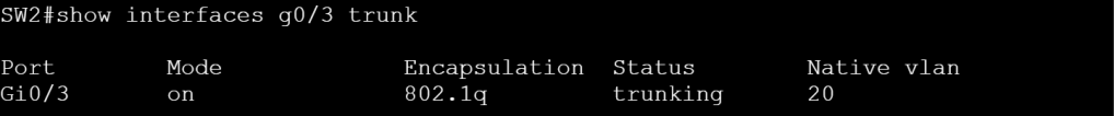
I could imagine a native VLAN mismatch coming up on the lab and causing grief.
SW2: Native VLAN mismatch.
We can check the native vlan with show interface nametrunk.
SW2: Native VLAN 20.
One other thing to call out here is if we want to tag our native vlan. conf t vlan dot1q tag native
If we’re tagging native VLANs on both sides of the link we’ll be able to ping VLAN interfaces, even if the native VLAN is mismatched. We’ll still get the error every couple seconds about the native vlan mismatch, but at least we’ll have connectivity.
1.1.c iv Manual VLAN pruning
For manual VLAN pruning, we just want to prevent unnecessary broadcasts to switches where we know a specific VLAN doesn’t exist. We can either explicitly state the VLANs to allow, or allow all except certain vlans.
conf t int g1/0/1 swi trunk allowed vlan 101-103,105 OR switchport trunk allowed vlan except 100,103-400,402
1.1.c v VLAN database
1.1.c vi Normal range and extended range VLANs
1.1.c vii Voice VLAN
1.1.c viii VTP
For VTP we’ll probably have to make sure we understand the modes based on their description. A task can ask us to “ensure Switch2 passes VLAN updates to neighbors, but they do not modify the local VLANs.”
Server: The server switch can create, modify, and delete VLANs within the VTP domain. Client: Receives VTP advertisements and modifies the VLANs on that switch accordingly. Local configuration of VLANs isn’t allowed. Transparent: VLANs are configured locally. VTP advertisements are passed on between neighboring switches, but don’t modify this transparent switch’s local VLAN database. Off: Doesn’t send or forward VTP advertisements. VLANs are configured locally.
VTP Versions
We should really only be dealing with Version 3 at this point, which covers the full range of VLANs (1-4094). We can have multiple servers in a VTP domain, so we need to make sure we know how to set a primary VTP server (note it’s under Enable mode, not Config T): enable vtp primary
VTP Updates
The multicast VTP updates fall into three categories: Summary: Every 300 seconds, or when there’s a change. Includes revision number, timestamp, domain, and VTP version. Subset: Triggered by a VLAN configuration change. Includes the info to update the corresponding VLANs. Client Requests: If a client notices it has a lower revision number, it can request a detailed Subset update.
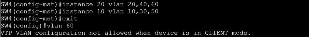
VTP VLAN Configuration
We just configure the domain, the version number, the mode, and the password. We’re going to assume that the lab will ask us to configure a password, even though it’s optional. The only trick is the sequence, you can’t do vtp primary until you do the version, and you can’t do the version until you do the domain.
Switch1: conf t vtp domain oscorplabs.com vtp version 3 vtp password C!sco123 vtp mode server exit vtp primary
Switch2: conf t vtp domain oscorplabs.com vtp version 3 vtp password C!sco123 vtp mode client
VTP MST Configuration
Let’s get a little crazy here. Let’s set up one of the VTP clients (client for VLANs) as the MST primary server. Then we’ll set up a couple MST instances on that one box and have them pushed out automatically via VTP.
SW1: VTP Vlan Primary Server
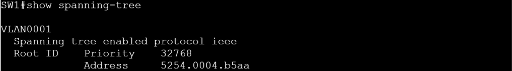
Switch 1 is currently using standard PVST.
SW1: show spanning-tree
Let’s make two quick changes on SW1: conf t spanning-tree mode mst vtp mode client mst
Let’s make SW4 the VTP MST primary server: conf t spanning-tree mode mst spanning-tree configuration instance 10 vlan 10 end vtp primary mst
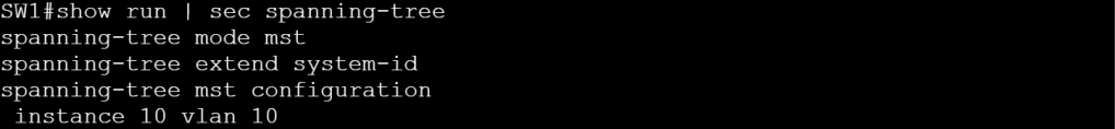
Then we’ll do a show run | sec spanning-tree on SW1.
SW1: show run | sec spanning-tree
Then we’ll add a couple more instance commands on SW4, the MST primary. Now let’s check SW1 again.
SW1: MST config updated automatically
Let’s look at the VTP status on SW1.
SW1: MST VTP Mode is client.
There are a couple interesting things to note here. The VTP MST has nothing to do with VTP VLANs. VTP is just the method of sending configuration updates automatically to peers (clients). To prove this point, I set up SW4 as a VTP VLAN Client, and a VTP MST Server. SW4 is in charge of updating MST instance information, but still can’t make any local VLAN changes.
Each edge router peers with the vSmart controllers using OMP. OMP is strictly for control traffic, never for data plane traffic. And each WAN Edge router only peers with vSmart controllers, they’ll never peer with another WAN Edge.
The OMP routes advertise TLOCs mapped to prefixes. The TLOCS have to be reachable via the underlay. “To get to 10.5.11.0/24, use TLOC 191.0.2.39.” The WAN Edge router needs to have an underlay route to get to TLOC 191.9.2.39. A TLOC is basically a “next hop”.
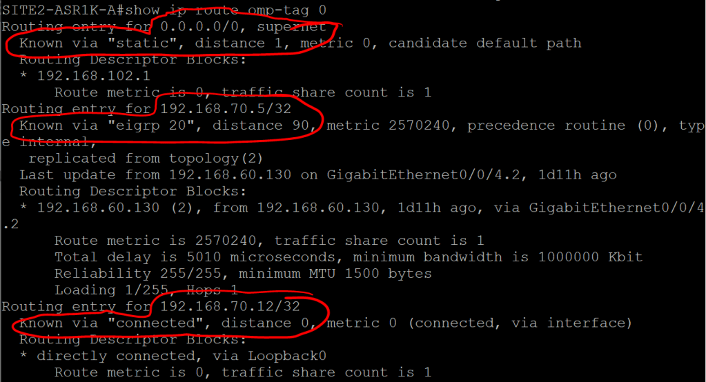
ASR1K: show ip route omp-tag 0
By default OMP will automatically redistribute connected, static, and OSPF (except external) routes. You can also tell it to redistribute EIGRP and BGP routes, as well as LISP, IS-IS, and OSPF external routes.
What can we expect to see in an OMP update that’s sent from a WAN Edge router up to vSmart?
TLOC – which we recall is just the System IP + Color (biz-internet or MPLS) + encapsulation (which is probably always IPSec).
Origin – How the route was learned (e.g. OSPF) plus the corresponding metric.
Originator – The IP address of wherever the route was learned from.
Preference – Higher is better.
Site ID – Where the route belongs.
Tag – Optional, can be used for control decisions.
VRF – The segment the route belongs to.
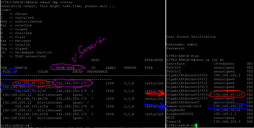
ASR1K: show sdwan omp routes
Site2 and Site3 OMP routes.
We can see that the 192.168.60.128/30 route was learned from the vSmart peer (192.168.250.172), and that the next hop, or TLOC, is System-IP 192.168.250.12
Note that the next hop is not 192.168.102.2, which is the underlay IP for VPN 0. The idea behind this is similar to using a loopback IP for iBGP, since interfaces can go up and down or change IPs. A System IP is more stable and reliable.
But clearly we’re missing a valuable piece of information. We know that we need to go to System IP 192.168.250.12 to get to that 192.168.60.128/30 address. But how the hell do we get to 192.168.250.12? Where does that routing information come in? That’s what TLOC Routes are for.
2.2.b iv TLOC
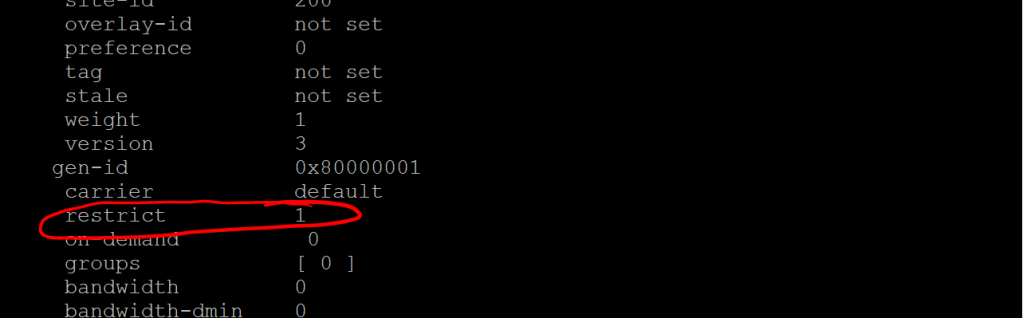
Let’s take a look at the TLOC table on Site3-ASR1K: show sdwan omp tlocs
Site 3: show sdwan omp tlocs
Note the public-ip and private-ip entries, in case we’re doing NAT. There’s a whole lot more after this, but the one thing I want to call out is the restrict value. If we remember from a previous post, the restrict values tells the router to only set up peering relationships with the same TLOC Color (e.g. biz-internet). This is for a scenario where you have two routers, each with two interfaces (maybe one is Verizon and one is AT&T), but they’re both routable via either interface. Meaning that Router 1’s Verizon link can ping Router 2’s AT&T link, and vice-versa. By default, that would mean we’ve got four separate IPSec tunnels going up between these sites, when really we want just two (Verizon to Verizon and AT&T to AT&T). So we would set them up with the restrict value.
This isn’t really called out on the Enterprise Infrastructure blueprint (unless you count section 2.1.a iii Fabric domains (single-site and multi-site using SD-WAN transit), but I figured it would be something fun to try. It turned out to be a nightmare.
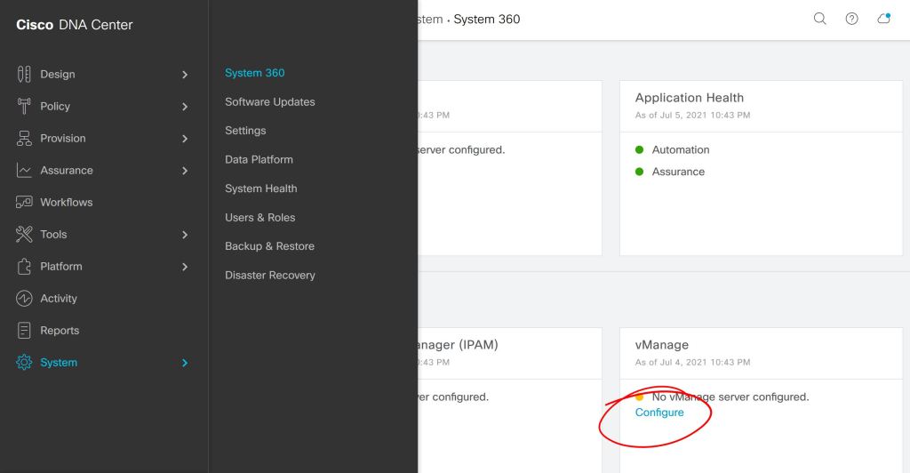
First thing, you kick off the connection from DNAC, either under System > Settings or System > System 360.
DNAC: System 360
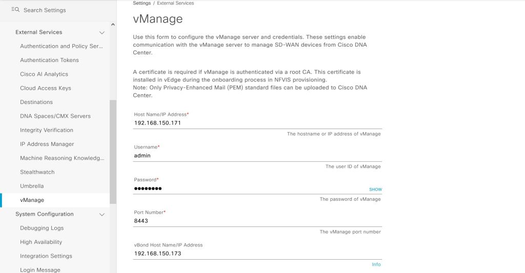
Seems simple enough so far, we just have to plug in our IP and user info for vManage.
DNAC: Add vManage.
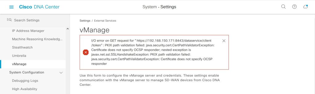
Wrong… big red error.
DNAC: Error
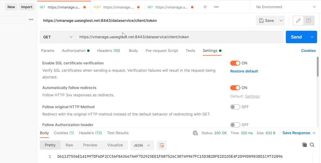
I tried a bunch of things with the cert, like using the FQDN instead of the IP. Google searches led me to believe that there was something wrong with my vManage cert. As a sanity check, I tried the same API call from POSTMAN that DNAC is trying and it worked fine.
Postman: API Call is fine.
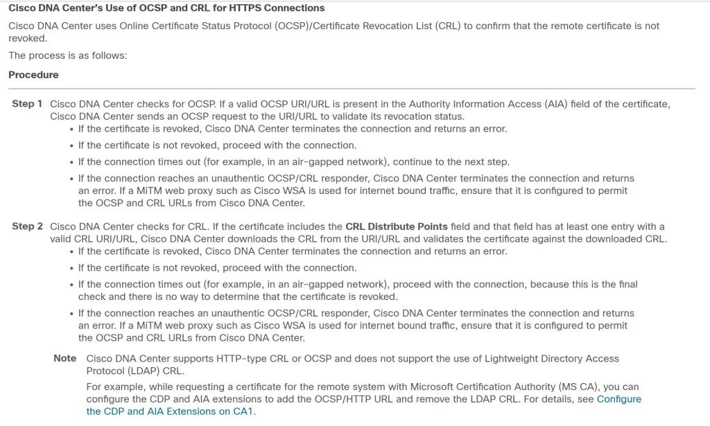
Turns out that the issue was exactly what the error was trying to tell me. DNAC didn’t like something about the certificate’s CRL.
Towards the bottom there we have an interesting note: DNAC doesn’t like LDAP CRL’s. Well let’s take a closer look at our vManage cert.
vManage: ldap CRL
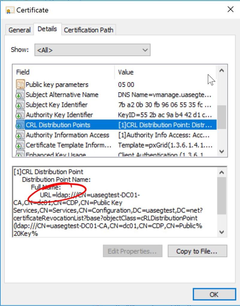
Let’s log into our Windows Server Certificate Authority and check the Properties > Extensions of our CA. First we’ll click on the LDAP entry and uncheck all those boxes.
Windows Server: Uncheck LDAP boxes.
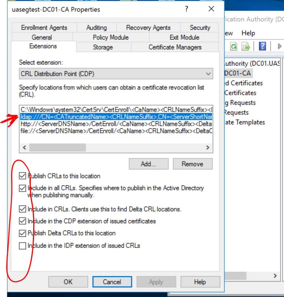
Then we’ll click on the http: entry and check the following two boxes, Include in CRLs and Include in the CDP extension of issued certificates.
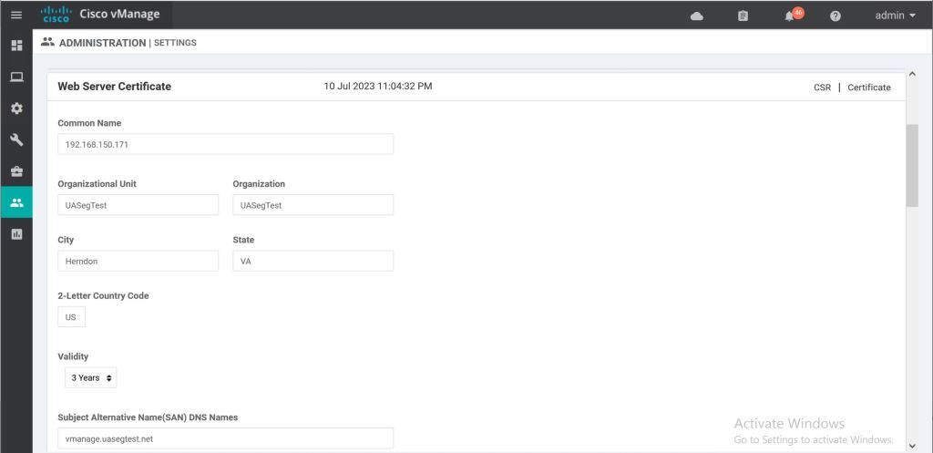
Now we need to go back to vManage and re-do the Web Server Certificate under Administration > Settings > Web Server Certificate > CSR.
vManage: Web Server CSR.
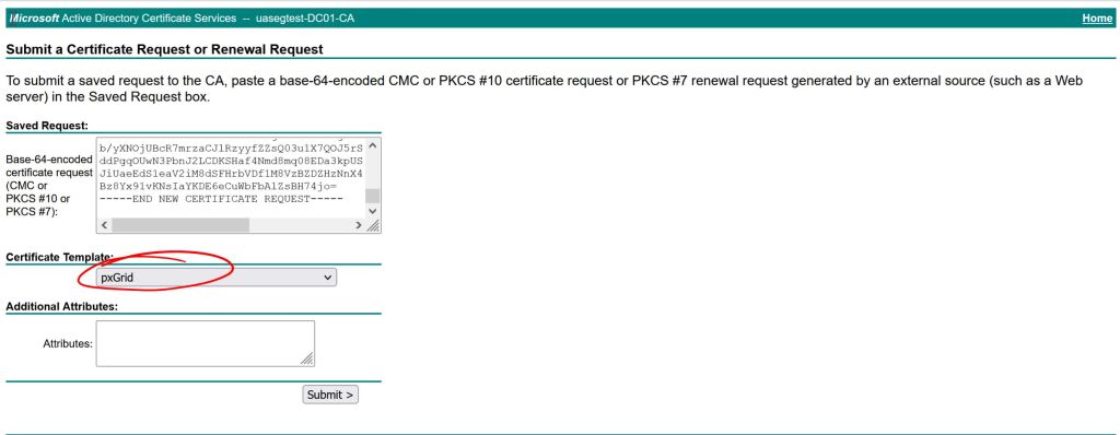
Then sign it again (this is about the 50th time I did this during the troubleshooting process). I use the pxGrid template I have build in AD which include client auth and server auth. You should be able to get away with just using a standard web server template that has server auth only.
Windows Server: Issue the cert.
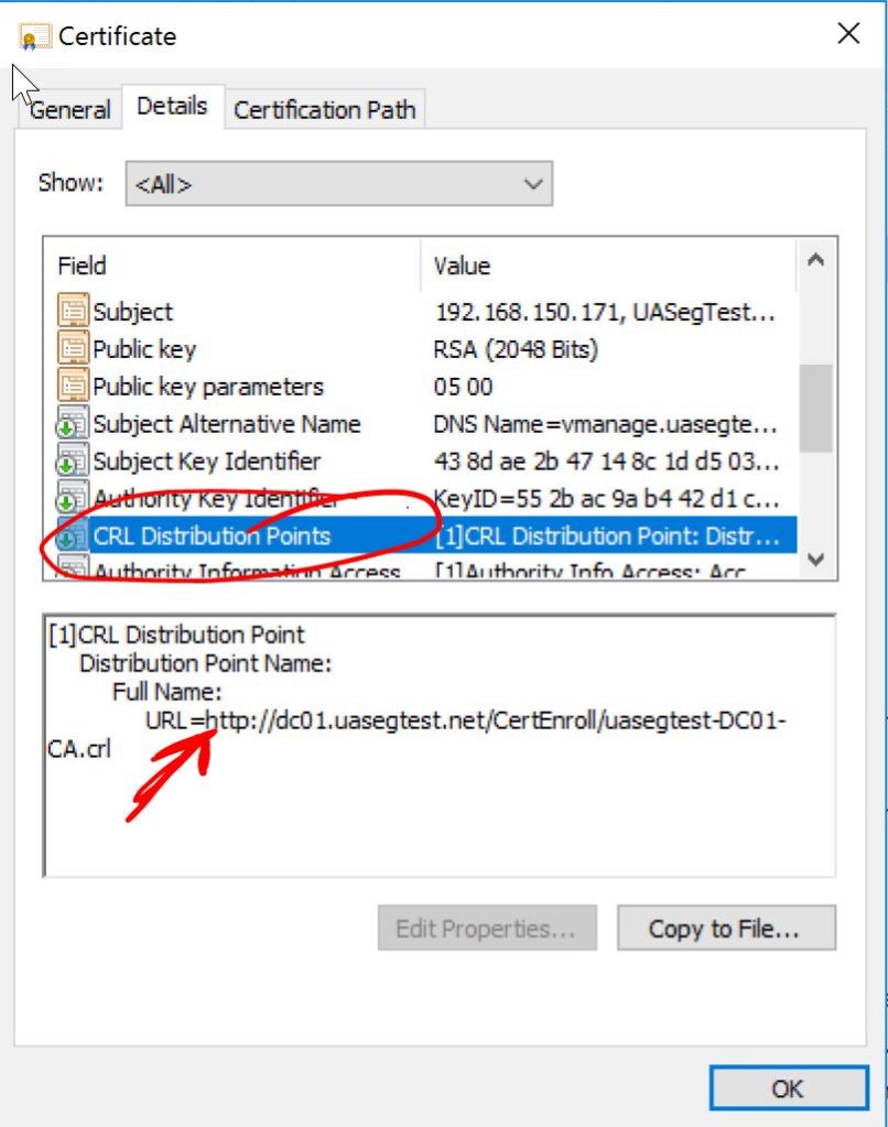
Let’s take a look at our fresh new cert and verify the CRL Distribution Points.
vManage: HTTP CRL.
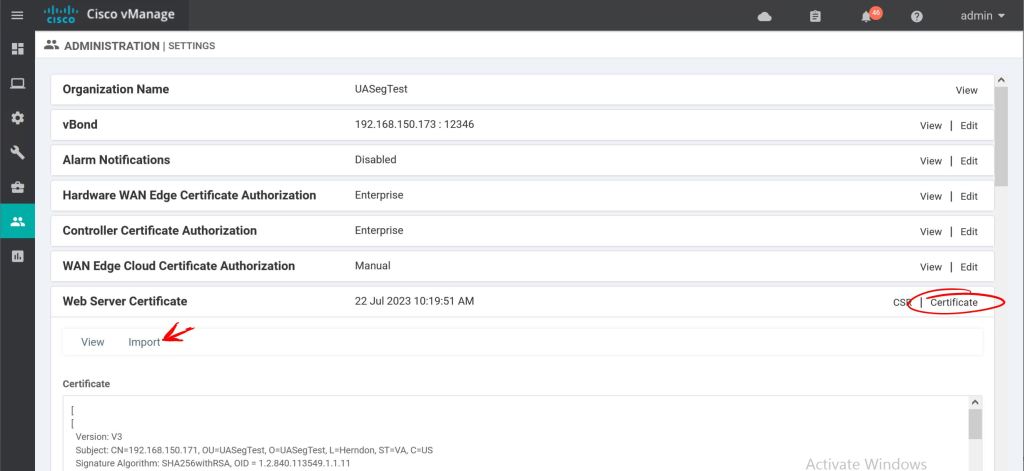
Looks good. Let’s import it into vManage
vManage: Import Web Server Certificate.
Hopefully this will be enough to please our DNAC Overlords. Let’s see what happens.
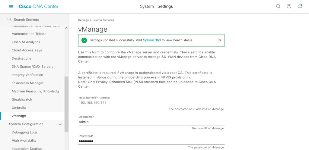
DNAC: vManage success!
It actually worked. This green success checkbox that takes up about 30 seconds of blog post took me forever to actually get working. It was such a huge relief to see it turn green like that. I was pretty close to throwing the whole thing out the window.
Next up, we’ll try to figure out what we can actually do with this…