This should be another slam-dunk topic. CDP is pretty straightforward. It has to be running globally and on individual interfaces.
SW1: CDP Not enabled.
conf t cdp run inter gig 1/0/1 cdp enable
One more thing worth mentioning is that you can customize your TLV (type-length-value) lists that are sent with CDP. An example might be if we want to create a physical address entry and include it with CDP. conf t location civic-location identifier host city Scranton state PA cdp tlv-list TLV_LIST location cdp filter-tlv-list TLV_LIST !This enables the TLV List on all interfaces. Optionally we could have applied it at the interface level.
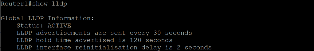
Let’s have a little more fun with LLDP. We’ll tweak the settings a little bit. We can set an interface to send only or receive only if we want to. Doing a show lldp gives us some options we can alter.
An obscure task could be, “Setup Router1 to receive LLDP updates on gig 0/0, but not send LLDP updates. Received updates should be stored for five minutes before discarding. Router 2 should wait 5 seconds before initializing LLDP. Updates should be sent every 60 seconds.”
Router1 conf t lldp run lldp holdtime 300 interface gig 0/0/0 no lldp transmit (Transmit and Receive are enabled by default, so we’ll need to disable transmit to accomplish the task.)
Router2 conf t lldp run lldp reinit 5 lldp timer 60
We talked about UDLD a bit in the STP post. It serves the same basic purpose as Loop Guard, which is to prevent an issue where a link can only transmit and not receive (or vice-versa, depending on your perspective). There are two modes, Normal and Aggressive. Normal mode doesn’t err-disable the link when it triggers.
Task: Enable UDLD on all fiber ports so that unidirectional link failure puts the port in err-disabled state: conf t udld aggressive
Task: Enable UDLD on interface Gig0/0/0 so that any link failure will not err-disable the link. conf t int gi0/0/0 udld port
This topic is pretty straightforward, so I’m trying to think of ways they can over-complicate it on the exam, maybe with some obscure setting you would never, ever configure in a production environment.
1.1.a i Managing MAC address table
The best I can come up with is modifying the aging time on the mac address table.
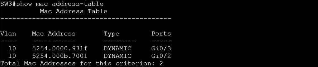
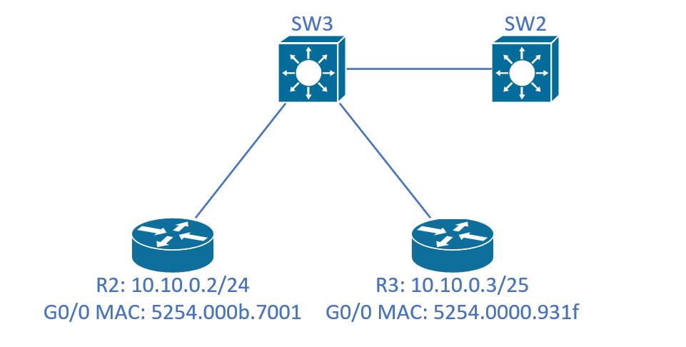
After doing a ping from R2 to R3, we can issues show mac address-table on SW3 to see the MAC addresses listed above, along with the interfaces they’re connected to, and the VLAN numbers.
SW3: show mac address-table
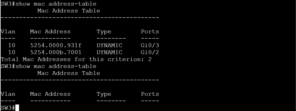
But let’s modify the aging timer and set it to 10 seconds for vlan 10. conf t mac address-table aging-time 10 vlan 10
SW3: The table emptied out.
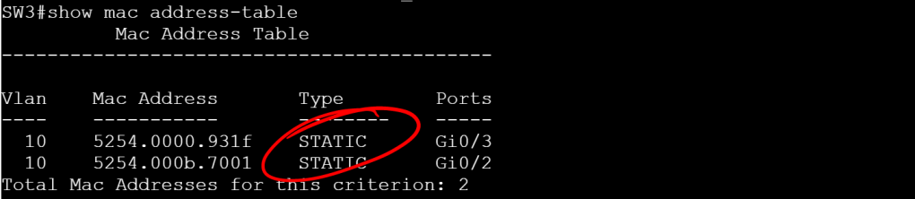
Another goofy thing we can try is statically assigning a MAC address to an interface and VLAN. conf t mac address-table static 5254.0000.931f vlan 10 interface GigabitEthernet 0/3 mac address-table static 5254.000b.7001 vlan 10 interface GigabitEthernet 0/2
SW3: Static MAC assignment.
1.1.a ii Errdisable recovery
This should be another short topic that we’ll need to figure out where there can be some hidden tricks. For an easy err-disable, we’ll set BPDUGuard on SW3 Gig
Topology.
SW3: (no tabbing) conf t int gi 0/1 sw t e d sw m t spa portf e t spa bpdug e (Set it to a trunk, enable portfast with the edge trunk command, so it enables it even if it’s a trunk port, then enable bpduguard.)
SW3: BPDUGuard err-disabled the port.
How do we know BPDUGuard is the what caused the err-disabled status?
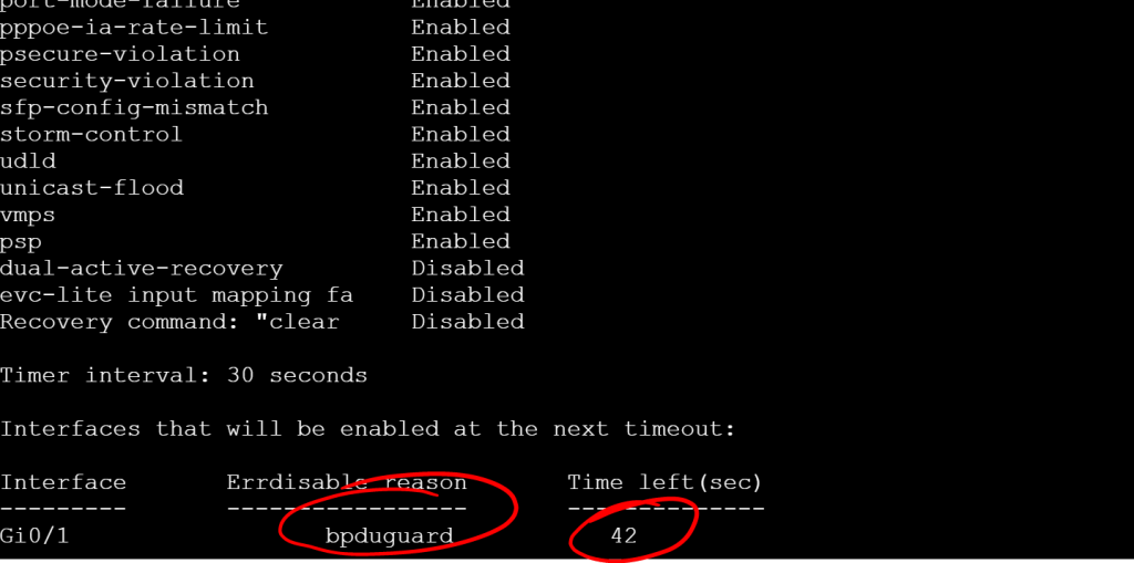
We can browse our syslog messages, or an easier way is to turn on err-disable recovery: conf t errdisable recovery cause all errdisable recovery interface 30 (We set it to recover from any err-disable cause, and recover every 30 seconds.)
show errdisable recovery
SW3: show errdisable recovery
But wait a second! If the Timer interval is set to 30, how can there be 42 seconds left? The timer takes effect after the next cycle. The default timer is 300 seconds.
1.1.a iii L2 MTU
The big thing to remember with L2 MTU is that fragmentation only happens at L3, so if the L2 MTU can’t handle the size of the incoming frame, it gets dropped. A couple areas we’ll need to worry about this is with VXLAN when we get to the SDA section and then again with MPLS labels, since they can be stacked and each one is 4 bytes.
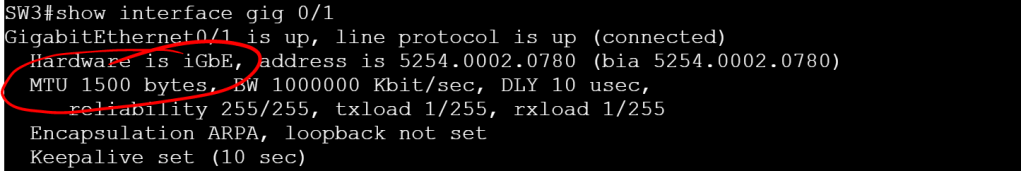
Let’s check the L3 MTU setting on an interface: show interface gig 0/1
SW3: show interface gig 0/1
You can modify the L3 MTU per interface with the ip mtu command, but it maxes out at the system MTU value. So you can’t set the system MTU to 2000 and an interface MTU to 2100.
This doesn’t include the frame header and any tags (like dot1q vlan tags). If you modify the system MTU, it gives you a very specific message about this: config t system mtu 9198
Global Ethernet MTU is set to 9198 bytes. Note: this is the Ethernet payload size, not the total Ethernet frame size, which includes the Ethernet header/trailer and possibly other tags, such as ISL or 802.1q tags.
I’m getting beat up pretty bad by SD-WAN, so I’m taking a break to bang out some easy stuff off the blueprint. I want to give myself a false sense of progress.
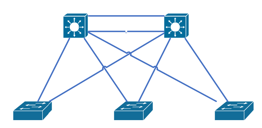
The topology is super simple:
STP Topology
1.1.e i PVST+, Rapid PVST+, MST
Super-quick summary on the versions: PVST+: 30-50 seconds before a port transitions to FWD. 50 VLANs means 50 BPDUs. Rapid-PVST+: Convergence can happen in less than a second. But you can still have scenarios that are up to 6 seconds (2 seconds between BPDUs times 3 missed BPDUs to trigger re-convergence). Also, 50 VLANs still means 50 BPDUs. MST: MST allows you to group VLANS to cut down on the number of BPDUs. The timers are the same as Rapid-PVST+. One more thing about MST: the name, revision number, and digest of the 4096-element VLAN table have to match between peers.
Let’s check the current mode:
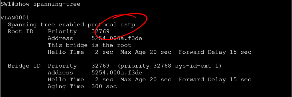
show spanning-tree
SW1: STP mode ieee
IEEE means PVST+ RSTP means Rapid-PVST+ MSTP means MST
It’s worth calling out the MST config, because it’s a little different. You go under MST configuration mode, set the name, the revision number, and the vlans for the instance.
1.1.e ii Switch priority, port priority, path cost, STP timers
Since we’re working with per-VLAN STP by default, let’s take 4 VLANs (10, 20, 30, and 40) and make SW1 the root for VLANs 10 and 20, then make SW2 the root for VLANs 30 and 40.
SW1: Still the root for VLAN 10.SW1: No longer the root for VLAN30.
But this 30-50 second timer takes too long. Let’s flip the mode to Rapid-PVST+ so we can have two second timers.
spanning-tree mode rapid-pvst
SW1: RPVST+ mode.
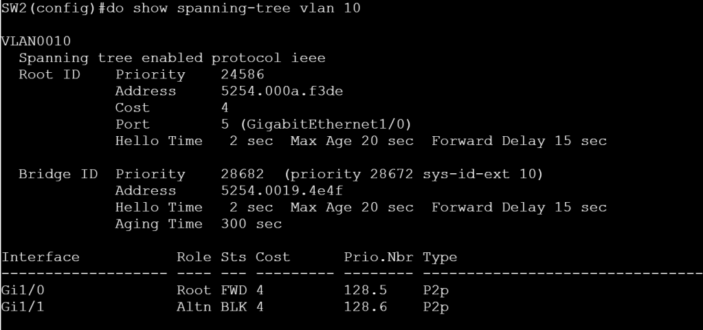
Right now on SW2 for VLAN 10, Gig1/0 is forwarding and Gig1/1 is blocking. Let’s flip flop those using some interface level STP config. (Note, this isn’t Rapid-PVST specific, I just don’t want to wait a minute after making the change.)
SW2: Gig1/0 FWD, Gig1/1 BLK.
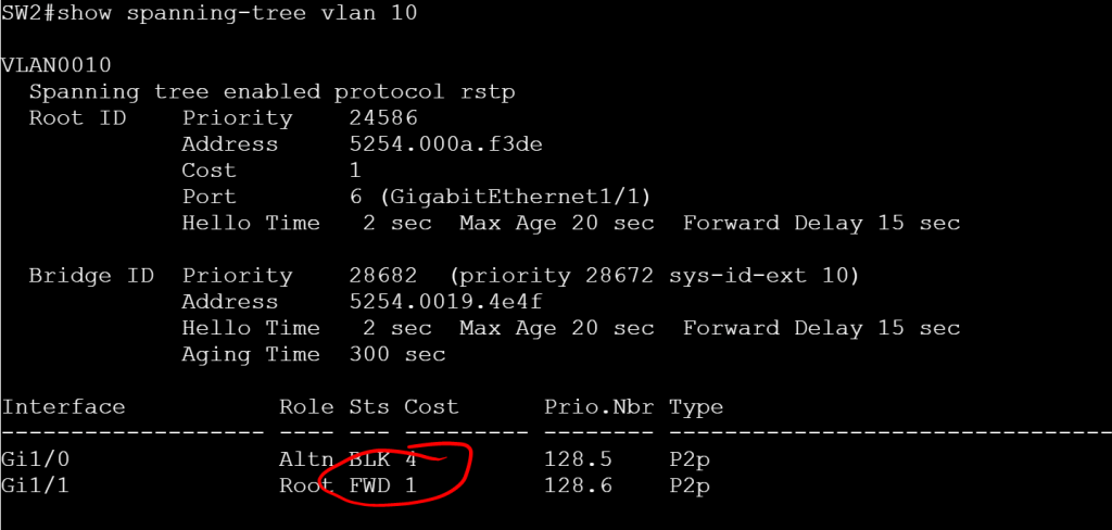
SW2 interface gig 1/1 spanning-tree cost 1
SW2: Gig1/1 cost is set to 1, status is FWD.
A note about Path Cost, these numbers get added up along the way and then tacked onto the Priority number, which gives the total priority. We’re using Short Path Cost Method, where 1Gig interface default cost is 4 and a 10 Gig interface default cost is 2. With Long Path Cost Method, those numbers are 20,000 and 2,000, respectively. The method can be modified as follows:
spanning-tree pathcost method long (Also, switching to MST mode automatically sets it to Long).
One last thing to configure for this sub-section. Let’s modify the timers.
Hello Timer (default is 2, range is 1-10): spanning-tree vlan 10 hello-time 1
Forward-Delay Timer (default 15, range is 4-30): spanning-tree vlan 10 forward-time 7
Maximum-Age Timer (default is 20, range is 6-40): spanning-tree vlan 10 max-age 8
1.1.e iii PortFast, BPDU Guard, BPDU Filter
Let’s throw PortFast on the access ports (just don’t plug a switch into this interface): interface gig 1/0/13 switchport mode access switchport access vlan 10 spanning-tree portfast edge
If someone does try to plug a switch into our access port, we should have BPDU Guard enabled to shut the port down: interface gig 1/0/13 switchport bpduguard enable
But maybe we don’t want to err-disable ports that get BPDUs, maybe we just want to ignore BPDUs. And for good measure, we’ll not send BPDUs either. This can be dangerous if enabled on a single interface, since it basically disables STP. Instead, let’s just enable it globally, then it only gets enabled on PORTFAST ports. spanning-tree portfast edge bpdufilter default
1.1.e iv Loop Guard, Root Guard
Loopguard is primarily used to prevent half of a link going down and causing a loop because BPDUs are still received from one side, but not the other. The real trick to it is figuring out which interfaces it should be applied to. Basically you’ll want to put it on Root, Alternate, and Backup ports (not on Desg ports). You can apply it globally or per interface: spanning-tree loopguard default or interface gig 1/0/1 spanning-tree guard loop
Rootguard is the opposite, you only apply it to Desg ports. RootGuard prevents a rogue switch with a lower priority from becoming root. interface gig 1/0/24 spanning-tree guard root
I’m probably going to come back here and do a ton more with Configuration Templates, because it seems like the possibilities are endless. But for now, I just want to do a quick local password, NTP, and Loopback0 interface config and attach it to the ASR 1001-X.
On vManage, go to Configuration > Templates.
vManage: Configuration templates.
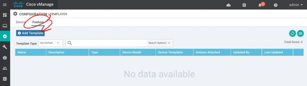
Click the Feature tab, then Add Template.
vManage: Add feature template.
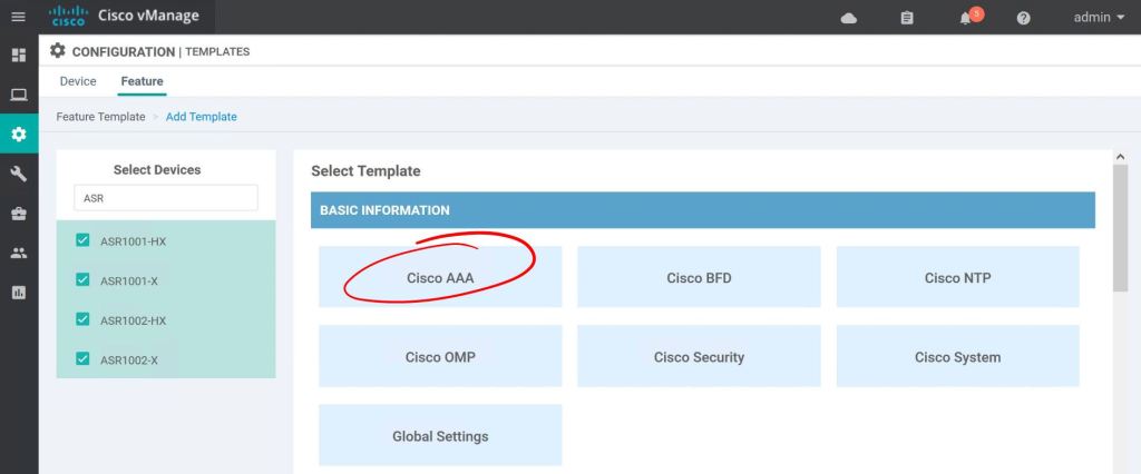
I just want this feature template to only apply to ASR routers. Click the checkbox for each router type and hit Cisco AAA.
vManage: Select template type.
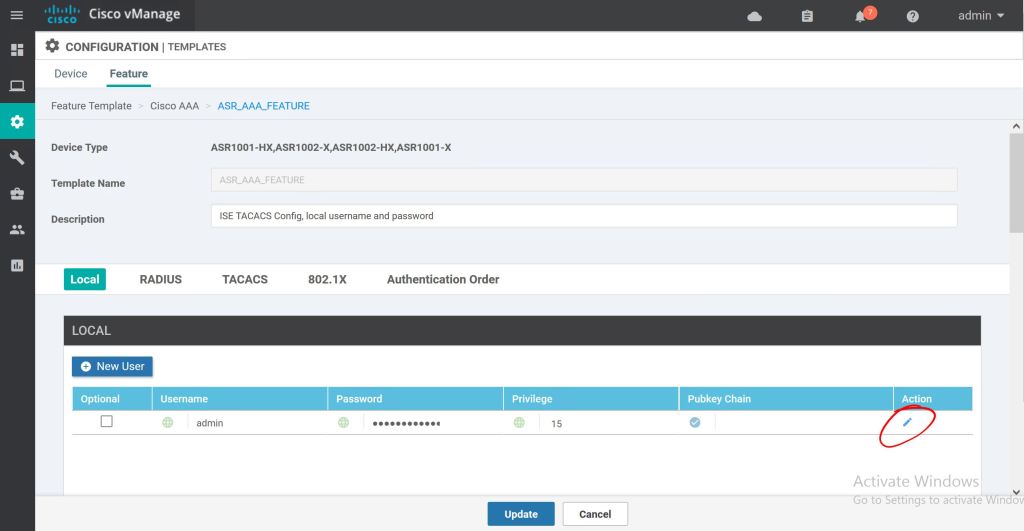
Super simple so far. Just give it a name and description. Then just click the little pencil icon to edit the admin password.
vManage: Name the template.
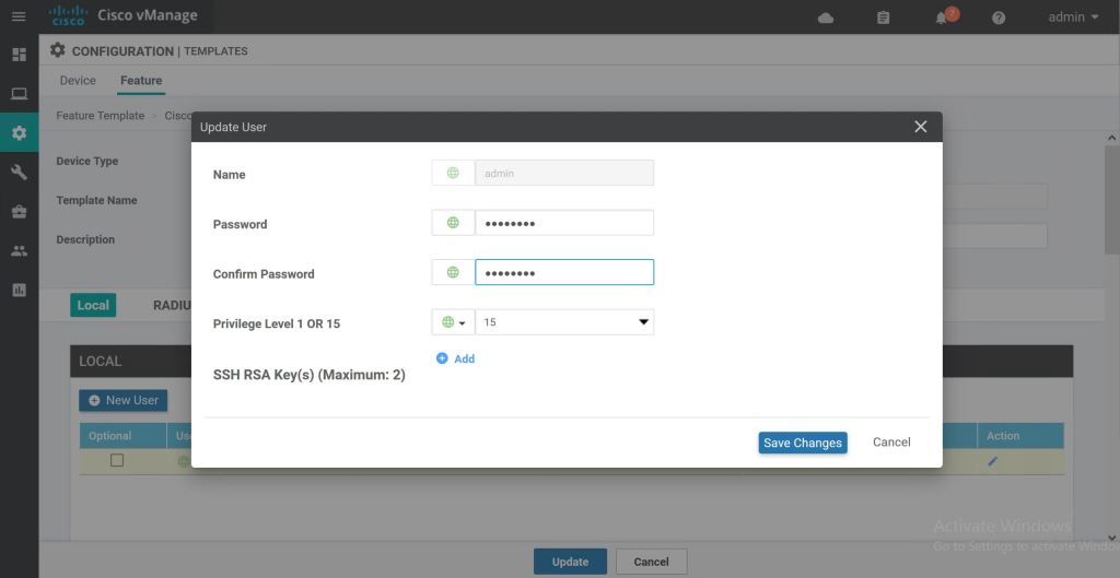
Type in the new password and hit Save Changes.
vManage: Edit local password.
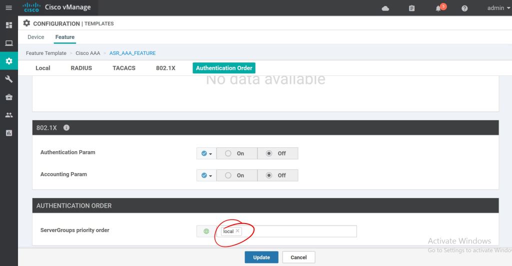
I tried to click Save without selecting an Authentication Order first and it gave me a big red error. So click the ServerGroups priority order and select local. Now we can hit Save.
vManage: Server group priority order.
Now we’ve got a nice, shiny new Feature Template. Super easy so far.
vManage: First template created.
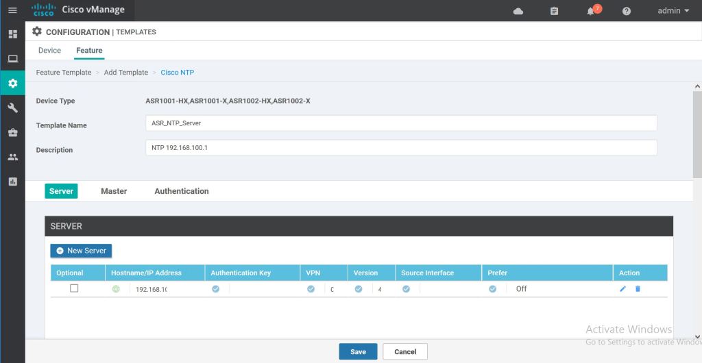
We’ll repeat those same steps for adding an NTP server. Just click to add a new feature template, select the router types, then select the Cisco NTP feature.
vManage: Cisco NTP feature template
The only trick with this one is you have to hit the Add button after inputing the NTP server specifics. Then it gets added as a new line. Do that before hitting Save.
vManage: NTP server added.
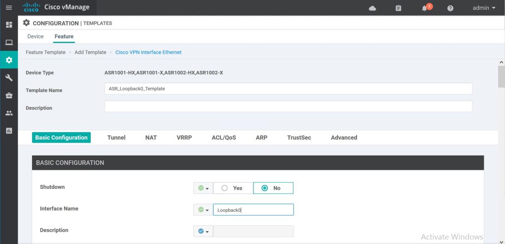
One more time through, but this time using the Cisco VPN Interface Ethernet feature template to add Loopback0.
vManage: Add interface.
It’s shutdown by default, so set that to No, then we’ll just type in the Interface Name of Loopback0.
vManage: Loopback0 feature template.
For the IP address we’ll use a variable. We’ll fill that variable value in when we get to pushing the template out. We’re good to hit Save.
vManage: Variable for IP address.
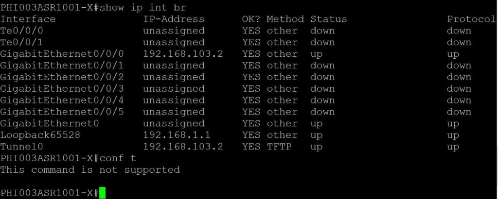
One quick thing to point out, the CLI is on lockdown. We can do show commands, but no configuration.
ASR: Cannot get to config t.
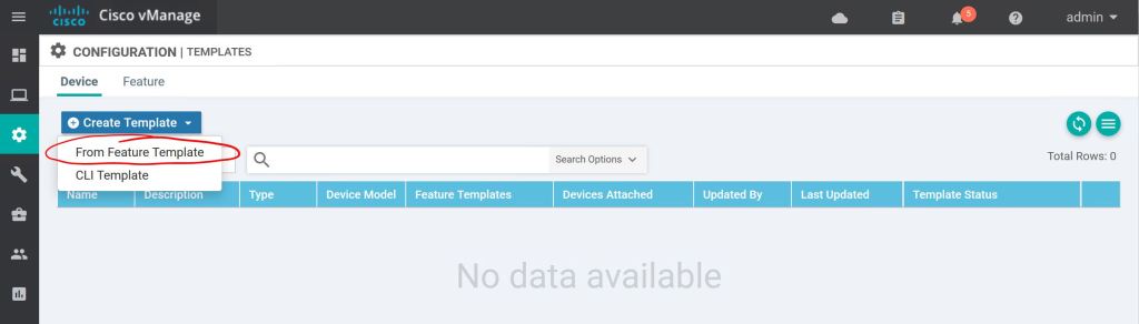
Let’s go to Configuration > Templates > Device to create a Device Template. Click Create Template and choose From Feature Template.
vManage: Device template.
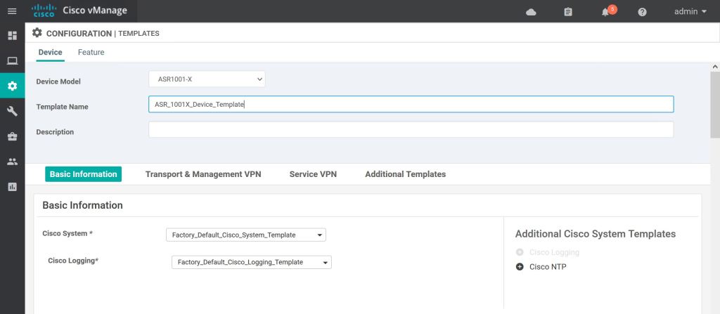
First we just select the device type, then give it a name and a description.
vManage: Create ASR 1001-X template.
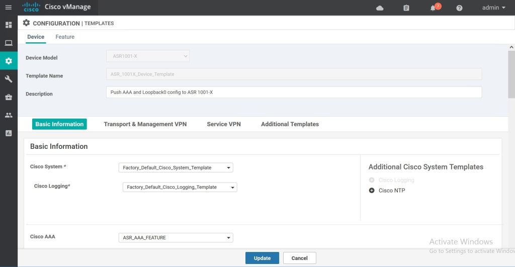
Most of the template settings we can just leave at Factory Default. For Cisco AAA, we’ll select the drop down and pick our custom Feature Template, ASR_AAA_FEATURE.
vManage: Select AAA feature template.
The next one is a little bit tricker. We have to hit the Plus Sign on the right to add the Cisco NTP feature option. Then we can select the NTP Feature Template we created. We have to do the same thing for the loopback. Click the Plus Sign to add the Cisco VPN Interface Ethernet feature template, then click the drop-down and select ASR_Loopback0_Template. Then hit Create at the bottom.
vManage: Add loopback0 feature template.
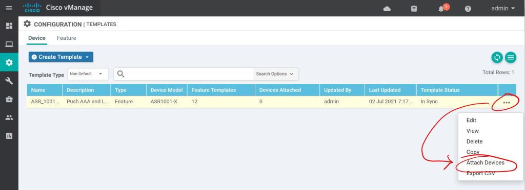
Next part is super easy, too. We just attach the template to the device. Hit the three little dots on the right and select Attach Template.
vManage: Attach template.
Pick the router(s) you want to attach this template to and shoot them over to the right with the Right-Arrow in the middle.
vManage: Select router to attach template to.
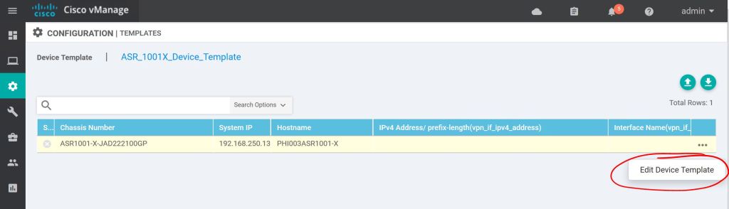
One more thing, we have to edit to template to add our variable.
vManage: Edit Device Template.
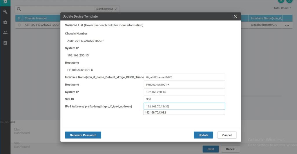
Then it’s as easy as filling in the blanks and clicking Update… sort of. Notice the first four fields are not ones that we created a feature template for. But they’re required, so we have to fill them in. The last field is the Loopback0 variable we had created as part of the feature template process.
vManage: Complete variable fields.
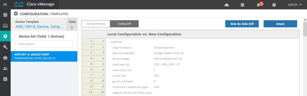
When we hit Next it takes us to a nice preview page. Let’s hit Config Diff at the top to see what changes will be made.
vManage: Config Preview
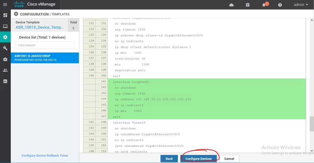
Added config will be highlighted in green, deleted config will be highlighted in red. When we’re ready to push it we just hit Configure Devices.
vManage: Config Diff highlighting.
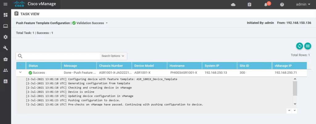
If everything goes well, we’ll get a Success message.
vManage: Template success.
One last thing, let’s look at the CLI and verify the changes.
ASR: Validate config.
Everything looks good. Super simple! There are a bazillion options with these template, so it can get pretty hairy pretty quickly. But the steps to just create the feature tempaltes, apply them to device templates, and then just push them to the device are pretty straightforward.
One more thing to mention, this was all done using the GUI templates, but there is an option to use CLI templates. Basically you hand-jam a config and push it to the device. We’re doing Software-Defined-Everything, though, so let’s get away from the CLI for now.
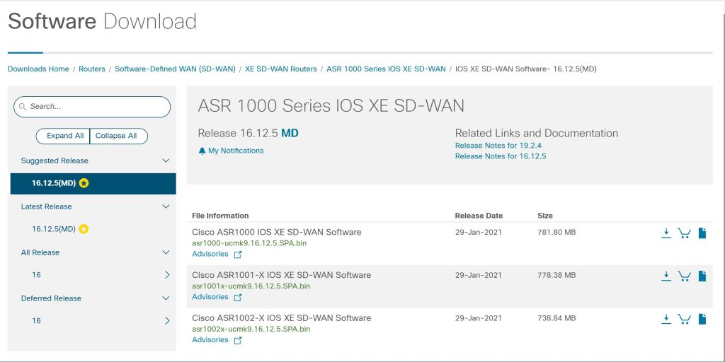
For this lab, the plan is to convert an ASR 1001-X over to SD-WAN code (I’m using 16.12.5 SD-WAN code, instead of the 17.x universal code, so I can test upgrading the router later.) and get it added to the SD-WAN deployment. The steps are pretty straightforward:
Re-image the device.
Stop the PNP service.
Apply the base config to reach the vBond and apply the root cert.
Add the vBond profile on cisco.com.
Add the device to your inventory on cisco.com.
Sync vManage with your Smart account.
Re-image the Device
Re-imaging the device is the same as an IOS change. Just download the image from cisco.com, TFTP it to the router, and change the bootvar to point to the new image. I’m not going to go into the details, since it’s something that’s been documented a million other times.
asr1001x-ucmk9.16.12.5.SPA.bin
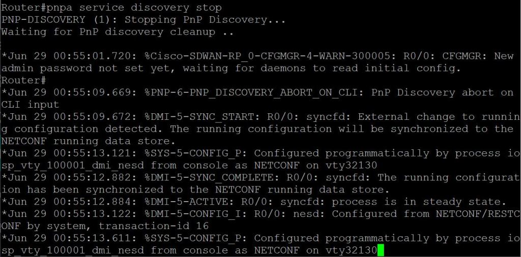
Stop the PNP Service.
Once it comes back online, you have to kill the PNP service, since we’re not doing PNP during the part (we’ll get to that at a later part of the blueprint).
ASR: pnpa service discovery stop
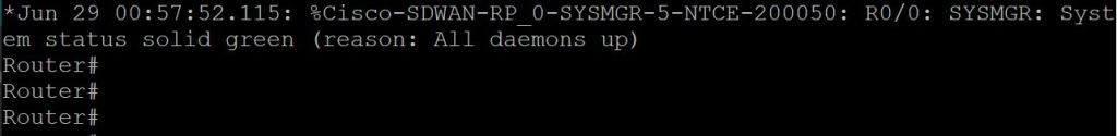
And give it a minute until you get the “all green”.
ASR: All daemons up.
Apply the Base Config
Then we just do some basic config, except it’s the Bizarro World version of IOS commands.
! First just configure the system info. You can’t do config t, it has to be config-t. config-transaction system host-name ASR1001X-AA ! system-ip is our unique device identifier. system-ip 192.168.250.13 site-id 100 ! org name has to match your SD-WAN deployment. organization-name MY-ORG-NAME vbond 192.168.150.173
! Then we’ll configure the tunnel interface. interface tunnel 0 ! Definitely copy and paste the interface name. I noticed it doesn’t like to tab it out sometimes. ip unnumbered GigabitEthernet0/0/0 tunnel source GigabitEthernet0/0/0 ! I initially left out this tunnel mode command, and the config wouldn’t commit. I got an error. tunnel mode sdwan
! Then configure the underlay interface and default route. ip route 0.0.0.0 0.0.0.0 192.168.103.1 interface GigabitEthernet0/0/0 ip address 192.168.103.2 255.255.255.252
! Finally, we glue the Tunnel 0 interface to the Gig0/0/0 interface. This is the part where you definitely have to copy and paste the interface name. sdwan interface GigabitEthernet0/0/0 tunnel-interface encapsulation ipsec color biz-internet allow-service all
The error I got when I left off the tunnel mode was: Aborted: ‘sdwan’: Sdwan interface GigabitEthernet0/0/0 doesn’t have tunnel Fixed it by adding the tunnel mode sdwan command on the tunnel 0
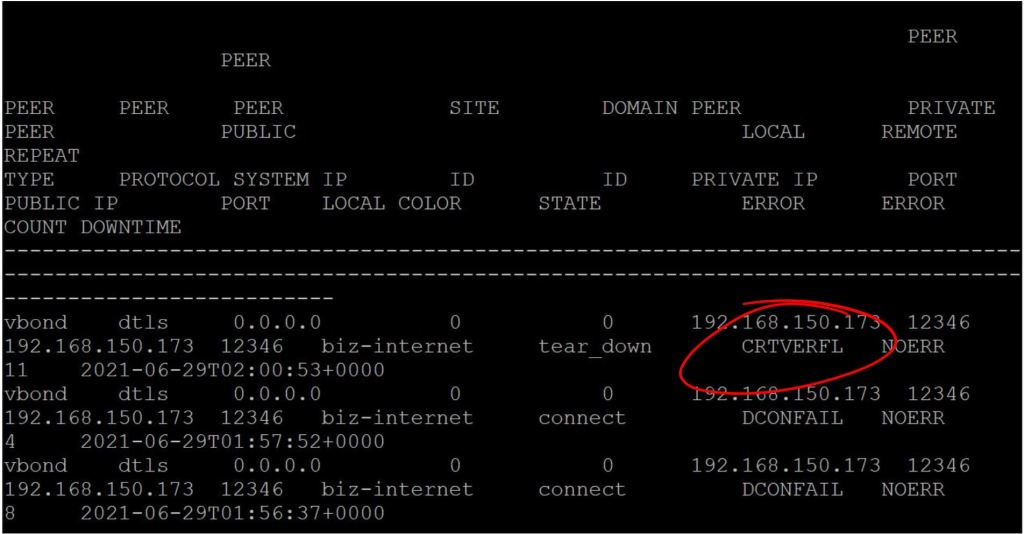
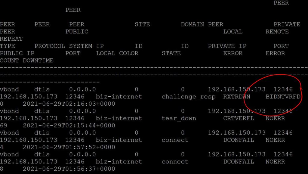
One more thing. We need the enterprise root cert loaded onto the router. Without it, you’ll see a CRTVERFL error when you do the show sdwan control connection-history command.
ASR: show sdwan control connection-history
Copy the root certificate to the router. copy tftp://{tftp-server-ip}/root.cer flash: request platform software sdwan root-cert-chain install bootflash:root.cer
Verify it with show sdwan certificate root.
Add the vBond Profile
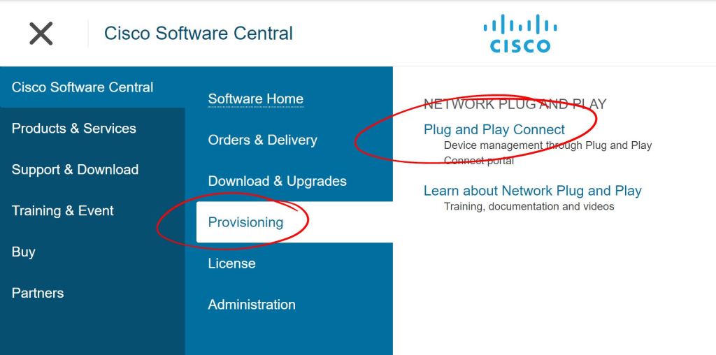
Go to the Provisioning > Plug and Play Connect section of cisco.com.
PNP Connect.
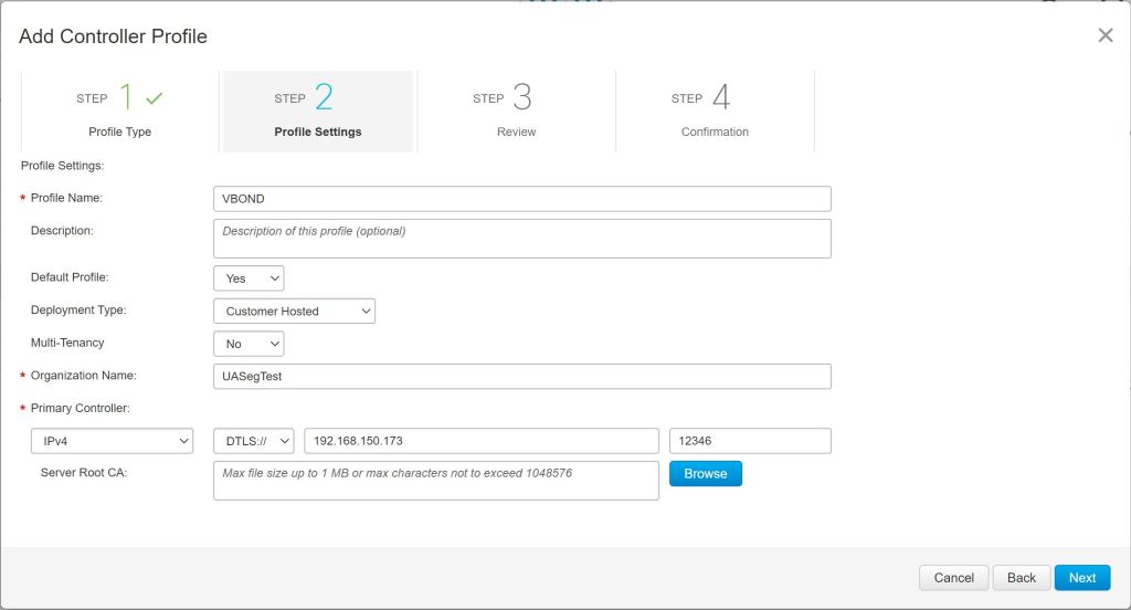
You have to create a default Controller Profile first. Click the Controller Profiles tab and hit Add Profile. Choose vBond as the Controller Type. Then fill in the fields as shown below. The Primary Controller IP doesn’t need to be reachable publicly. It just needs to be reachable by the WAN Edge that you’re labbing with. However, vManage will need to be able to reach cisco.com to sync things up.
Controller Profile
Add the Device to Inventory on Cisco.com
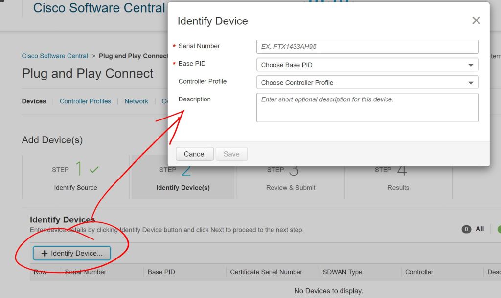
Then we go over to Devices and click Add Devices.
Add Devices
Choose to Enter Device info manually and click Next. Then click Identify Device to add a device. Enter the Serial Number, Base PID (device type), and select the Controller Profile (the one we just configured above).
IMPORTANT
I really screwed up big time and put in the wrong Serial Number (shown as Chassis ID on SDWAN) but the correct Certificate Serial Number. I’ll show the details at the bottom of this post.
Sync vManage with Cisco Smart Account
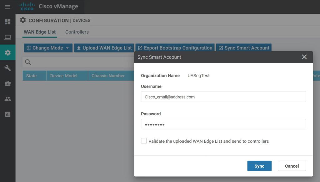
On vManage, go to Configuration > Devices > Sync Smart Account. In the pop up, enter your Cisco Smart Account credentials.
vManage: Sync Smart Account
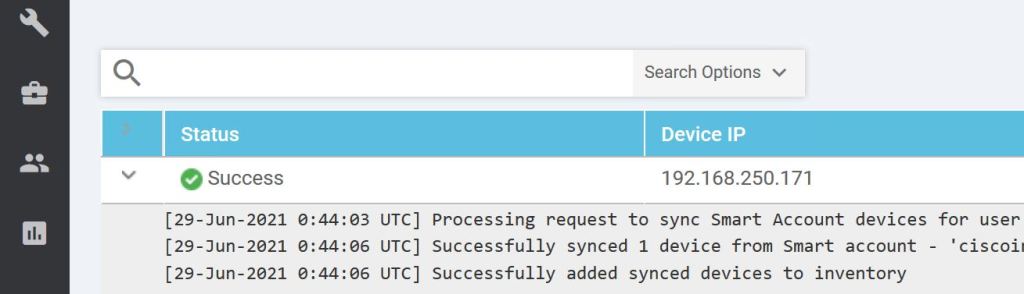
We can view the progress by clicking the little arrow to the left.
vManage: Syncing inventory
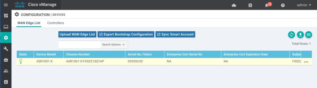
And just like magic, it should pop up in our device list.
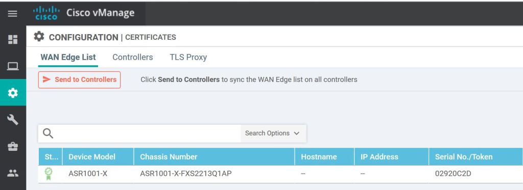
One more thing, we need to hit Send to Controllers on the vManage Configuration > Certificates page.
vManage: Hit the big red button!
We should see the successful handshake on the WAN Edge router.
ASR: vSmart handshake success..
Let’s also do a show sdwan control connections. It’s pretty messy on the default putty window size.
ASR: show sdwan control connections.
Troubleshooting
I struggled quite a bit to get this to work the first time. As I mentioned earlier, I made a mistake with the device serial number. I tried to just create a second device with the correct serial number and the same certificate serial number, but vManage failed when I tried to sync it up. Then I tried to delete the original WAN Edge from vManage by invalidating it and then deleting it, but it was stuck. I kept getting an error that things were out of sync (even though everything showed up as in sync). I found a couple bugs related to not being able to delete WAN Edges, but I didn’t want to waste anymore time. So I blew away vManage and started from scratch. I figured I needed the practice bringing everything up from the beginning. I was able to build out vManage, join the vBond and vSmart, and get the WAN Edge connected in about 25 minutes total.
Verify Chassis-Num and Serial-Num
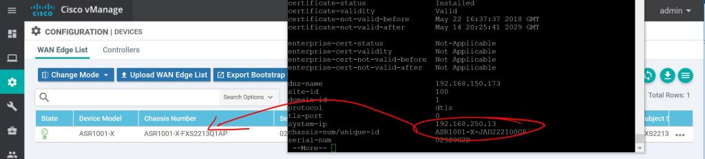
Verify the chassis-num/unique-id and serial-num match what’s configured in your Smart Account/Plug and Play page from cisco.com or from vManage Configuration > Devices.
show sdwan control local-properties
vManage: I totally screwed this up.
Just to reiterate, use the local-properties command to see what you need to put in when you’re adding devices, don’t just do a show inventory and grab the wrong serial number like I did.
Check Validate Setting
Another thing to check is the Validate column on the vManage Configuration > Certificates page. You have to scroll the little tiny scroll bar on the bottom over to the right to see it. It’s easy to miss.
When you’re syncing vManage with your Smart Account, there’s a checkbox which will set the router automatically to the Valid setting, which is like sending it straight to production.
If you don’t check that box and you leave the router in the Invalid state, you’ll see the BIDNTVRFD error on the connection-history. Obviously, that stands for Board ID Not Verified.
ASR: BIDNTVRFD
2.2.b ii Orchestration with zero-touch provisioning/Plug-And-Play
The WAN Edge router needs to talk to the organization’s vBond in order to get onboarded. How does router know how to find the vBond? There are two options. The first is what we did above, you apply a minimal config manually. The second option is for everything to happen automatically with Zero-Touch-Provisioning (Viptela) or Plug-and-Play (Cisco). The PNP process is pretty straightforward:
You cable the router up and power it on.
The router gets an IP address/default route/DNS server from DHCP.
The router phones home to ztp.viptela.com (DTLS for Viptela) or devicehelper.cisco.com (HTTPS for Cisco) and gets authenticated.
The public vBond (e.g. devicehelper.cisco.com) tells the router how to find its own organization’s vBond.
The router talks to its own vBond, authenticates, gets the info for vManage and vSmart, and gets the config push from vManage.
It turns out I really screwed up by using the organization name of “lab”. When I tried to do anything with PNP, I was stopped dead in my tracks because someone already used that name.
PNP: Name already exists.
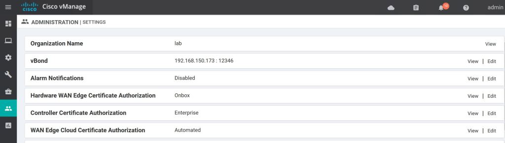
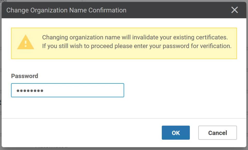
Luckily this is just a lab, so changing the organization name shouldn’t be a big deal… except there’s no option to edit.
vManage: Organization Name is View only.
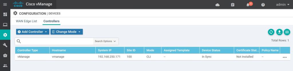
The solution (which sucks) is to delete all of the devices under Configuration > Devices > Controllers.
vManage: Delete devices.
Click the three little dots on the right for each controller, including the vManage itself, and select Invalidate.
vManage: Invalidate
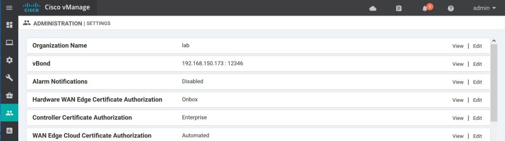
Now that everything has been invalidated, the option to edit reappears.
vManage: Edit org name.
This deletes the certs that we already generated, as well. Again, it’s a good thing it’s a lab and we need to practice.
The data plane is simple. It’s just an IPSec overlay. The big difference is that there’s a central key manager, the vSmart, which cuts down on overhead. There are two options, symmetric keys and pairwise.
Using symmetric keys, each WAN Edge sends its key to the vSmart, then the vSmart sends that key to all of the other WAN Edges. So when WAN Edge 2 wants to send data to WAN Edge 1, he encrypts it with WAN Edge 1’s key that he received from vSmart.
Pairwise keys are more secure than symmetric keys. It uses public/private key pairs, and unique keys are used between each WAN Edge and for each transport.
OMP Restrict Attribute
The color, e.g. transport method, doesn’t affect whether a tunnel will come up or not, they don’t have to be the same color. If there’s IP reachability, then the routers will try to bring up a tunnel. This means if there are two routers, each with two interfaces, and the two interfaces from WAN Edge 1 can reach the two interfaces of WAN Edge 2, you’ll end up with 4 tunnels.
You can set the OMP attribute restrict to 1, and then WAN Edge 1 interface gold will only try to form tunnels with TLOCs advertising the gold color. WAN Edge 1 interface lte will only try to form tunnels with other lte TLOCs. Restrict is a per-site setting, not a per-interface, or per-device setting.
Tunnel Groups
You can define tunnel groups, which is also advertised as in attribute in the TLOC route. Only tunnels with a matching tunnel group (or no tunnel group) will talk to each other. This means that if you define tunnel groups at Site 1, but not at site 2, they will still come up. You would need to define tunnel group 1 at site 1 and tunnel group 2 at site 2 to prevent them from forming data plane connectivity.
You can also use a combination of tunnel groups and the restrict attribute.
Segmentation
Don’t get too excited, it’s just VRFs. There are no TrustSec tags being natively carried in SD-WAN (but tags can be passed in GRE/IPSec tunnels). Once again, the VRFs here are called VPNs, but it’s the same thing. There are three types of VPNs.
Service VPN
VPNs 1 through 511. These are the regular user traffic VPNs. Each data packet carries a VPN ID across the overlay.
Transport VPN
VPN 0 is the underlay VPN, where the physical WAN transport terminates.
The vSmart is the centralized control plane of the SD-WAN deployment. It provides routing and data plane policies to the WAN Edge routers. The vSmart takes in all of the routing and topology information from the WAN Edge clients, calculates the best-path, then advertises the results back to the WAN Edge routers. The communication between WAN Edges and vSmart are encrypted and authenticated with DTLS.
Overlay Management Protocol (OMP)
OMP is pretty important, so it’s worth calling out here. OMP isn’t just a routing protocol. It handles all control plane information. It provides the best-path selection and routing policy advertisements, as well as the data plane security info (encryption keys), and more.
Administrative Distance on Cisco IOS is 251. (250 on Viptela OS)
The comparison is always made between OMP and BGP Route Reflectors. OMP Peering doesn’t happen between two WAN Edges. It only happens between a WAN Edge and the vSmart.
If connectivity is lost between the WAN Edge and vSmart, the WAN Edge router will continue to operate using it’s last know routing information and continue to try to re-establish connectivity with vSmart for the length of the graceful restart timer (default is 12 hours).
This brings up an important flaw in the design of every evil sci-fi robot. Whenever the master brain is destroyed in a Sci-fi movie, the robots just cease all functions. They’re usually poised to destroy someone and then just dramatically power down. A good design would be for the evil master brain to program the robot minions to carry out the most recent order, such as, “Destroy the Earth.” The example that comes to mind is Oblivion, the Tom Cruise movie from 2013. Not to mention the fact that there’s just one robot master brain with no redundancy…
OMP Routes: These are your router’s personal LAN prefix space. For instance, if you are the Reno, NV site and your local IP space is 10.29.5.0/24, then the OMP route could be something like, ” The 10.29.5.0/24 prefix is reachable via TLOC X, and these attributes are included.” The attributes included are:
TLOC: As discussed above, it’s a unique identifier.
Origin: Where’d the route come from? Static, Connected, BGP? What’s the metric. Think “redistribution.”
Originator: The System IP of the advertiser.
Preference: Basically the same as BGP Local Preference. Higher is better.
Service: See Service Routes below.
Site ID: Basically BGP ASN. All WAN Edges at the same site should have the same Site ID (loop prevention). Different sites all need unique Site IDs.
Tag: Optional value for applying policies. “Everyone with Tag 105 gets this policy!”
VPN (This is actually a VRF, but it’s called a VPN…)
Notice the similarity with BGP attributes.
show omp routes 191.1.1.0/24
(NEED A SCREEN CAP HERE)
But how is this TLOC reachable? I know I have to hit TLOC X to get the 10.29.5.1, but how do I get to TLOC X? That’s where TLOC Routes come in.
TLOC Routes: These routes are comprised of the WAN IP address, the corresponding TLOC, and whatever attributes. Includes:
TLOC Private Address: The IP configured on the interface.
TLOC Public Address: The NAT’d IP. If Public and Private are the same, then we’re pretty sure it’s not being NAT’d.
Color: Again, a stupid name since it’s usually not an actual color. Basically an identifier of the transport type. The router might have an Internet interface and an MPLS interfaces. The color identifies which is which.
Encapsulation Type: GRE or IPSec.
Preference: Similar to OMP Preference, higher is more preferred.
Site ID: Similar to OMP.
Tag: Similar to OMP.
Weight: Similar to BGP, locally significant only. Higher is more preferred.
show omp tlocs detail
(NEED A SCREEN CAP HERE)
Service Routes: Last one. Your WAN Edge can have some services hanging off of it, for instance, a NGFW. Your WAN Edge can then tell all his friends, “Hey, I’ve got this super NGFW in case anyone wants to use it.” That’s a Service Route. Configured using Feature Templates.
Path Selection
Another BGP knockoff. Another set of values to memorize… in order…
Valid OMP Route: If the TLOC isn’t active, the route isn’t considered. Pretty obvious one. Uses BFD to determine if it’s active.
Locally sourced: Routers prefer their own routes overs something learned from vSmart.
Lower Administrative Distance: Tie breaker, pick the lower administrative distance.
OMP Preference
TLOC Preference
Origin: Pretty much in AD order. First match wins…
Connected
Static
EBGP
EIGRP Internal
OSPF intra-area
OSPF inter-area
OSPF external
EIGRP external
IBGP
Unknown
Lowest Origin Metric: If there are two routes both from EIGRP, compare metrics.
Highest System IP: Now we’re into the annoying arbitrary tie-breakers.
Highest TLOC Private Address: … so annoying.
Loop Prevention
Redistributing routes from OMP to and from other protocols can inadvertently cause loops. There are a couple built in prevention methods.
OSPF: Uses the down bit to prevent a route from going back up toward the OMP routers. If two WAN Edges learn the same route, they’ll both redistribute it into OSPF. Then the OSPF neighbors will share it back and forth to each other, and then try to share it back up to the other WAN Edge. The down bit prevents this from happening.
BGP: You need to enable extended communities. Also, here’s where the Site ID comes into play again. BGP advertises the Site ID as site of origin. If the Site ID matches it’s own Site ID, the BGP router will drop the update.
EIGRP: Since XE SD-WAN routers can do EIGRP, it had to be enhanced for loop prevention. When redistribution happens from OMP to EIGRP, the External Protocol field is set to OMP-Agent. This doesn’t cause the route to be dropped, but sets the AD to 252.
The vManage server is the central manager for the SD-WAN deployment. This is where you’ll configure templates, onboard and provision devices, monitor everything with the fancy dashboards. It’s kind of like DNAC for the WAN, or it’s similar to the Admin Node in ISE. Just like everything else these days, it also supports REST and NETCONF. (I’m picturing a single pain of glass in the future that pulls in pieces of ISE, DNAC, vManage, ACI, Stealthwatch, FMC, and Tetration, and gives you this whole bird’s eye view of your entire network. Fun stuff!)
You can cluster vManage with three or more vManage NMSs (must be an odd number of servers), which can support up to 6000 WAN Edges (2000 per node).
Some of the cool things you can do is check the config and routing tables of any WAN Edge. You can also run simulations of traffic flow.
The WAN Edges communicate directly with vManage. Each WAN Edge will use only a single transport method to talk to vManage, even if there’s more than one way to get there.
There’s also vAnalytics (like DNAC’s Assurance) which does predictive analytics on the WAN (additional license required, not a default feature).
This is just a super brief overview. We’ll dig way more into vManage during the configuration parts in 2.2.b. One thing I’d like to talk about here that doesn’t really fit under any of the other blueprint headings is the communication flow between all these different SD-WAN components. Also, remember that all of these components use certs to authenticate themselves. It’s basically like this:
You set up vManage first.
Set up your vBond and add it to vManage. They’ll exchange certs to authenticate each other.
Then add your vSmart to vManage. Again, certs will be exchanged.
Then you have to tell your vBond about your vSmart. Then those two will exchange certs.
Now you can start adding routers to your device list (manually or CSV upload).
vManage will tell vBond about all these new routers.
vBond will tell vSmart about the routers he just learned about.
If you have a PNP server, it also needs to learn the device list (or you upload it.)
For PNP, WAN Edge routers will call home to the PNP server (DNS lookup of devicehelper.cisco.com)
The WAN Edge routers get informed on how to find their organization’s vBond server. (WAN Edge routers use the Cisco Manufacturer Cert to identify themselves, which vBond trusts).
vBond tells the WAN Edge how to find your organization’s vManage and vSmart.
WAN Edge talks to vManage, pulls down config and software (if needed).
WAN Edge then talks to vSmart, gets its OMP peering and routing information.
The DTLS communication between WAN Edge and vBond is torn down, no longer needed.
Now WAN Edges can talk directly to each other (data plane), but still talk to vManage (management plane, for config update) and vSmart (control plane, routing updates).
The vBond component is pretty much the key to the whole SD-WAN solution working. When a WAN Edge comes online, the only thing it’ll know about (learned from PNP, Zero-Touch Provisioning, or Manual or Bootstrap config) is the vBond. The vBond then directs the WAN Edge routers on how to get to vManage (Management Plane) and vSmart (Control Plane).
You can have multiple vBond servers and use a single DNS record to point to them. The WAN Edges will go through each IP sequentially until one succeeds.
The process is basically:
WAN Edge comes online and tries to call home to vBond.
If it calls home to the Cisco Provisioning Server, it will be directed to its own organization’s vBond.
The router and the vBond authenticate each other.
The vBond tells the WAN Edge how to get to vSmart and vManage.
After the router successfully connects to vSmart and vManage, the connection to the vBond is torn down.
NAT
The vBond also acts as a STUN server (WAN Edge being the STUN client). Basically the client includes its interface IP address in the payload of the DTLS tunnel message. The vBond can then compare the IP in the payload with the source IP. If they don’t match, then the vBond knows the WAN Edge IP is being NAT’d. The vBond makes sure to tell the WAN Edge router, that way the router can tell all his friends that he’s being NAT’d.
Also, vSmart and vManage can be NAT’d and will perform this same STUN operation when initially communicating with vBond.
One important thing to note. Symmetric NAT (aka, dynamic PAT), can be in use by only one peer, the other peer must have a router must have a public IP or static NAT (full cone NAT). This is because symmetric NAT only works when the router being NAT’d initiates the conversation. If two symmetric NAT routers were trying to communicate with each other, they’d have no way of getting that initial conversation across.