2.2.a Design a Cisco SD-WAN solution

I’m not sure how this blueprint item can translate into a lab task, but I’m going to use it to do a brief SD-WAN overview, which may help with any troubleshooting of later “deployment” tasks. I won’t be going into the history of SD-WAN or all of the benefits. For that you can read chapter 1 of the book listed below.

For everything SD-WAN, I’m using this book:
Cisco Software-Defined Wide Area Networks: Designing, Deploying and Securing Your Next Generation WAN with Cisco SD-WAN

SD-WAN Terminology

We have a couple different pieces that make up this SD-WAN puzzle.

vManage: The box we’ll be using to manage everything, including onboarding, provisioning, monitoring, and troubleshooting

vSmart: Think of this as the control plane. vSmart communicates with the WAN edge routers using OMP. The three routing updates from vSmart to WAN Edge routers are TLOC, OMP, and Service. These updates are then used by the WAN Edges to build the data plane.

vBond: This box tells the routers how to find the vSmart and vManage boxes. vBond also authenticates and authorizes the other components.

System IP: Unique router identifier.
Site ID: Like a BGP AS number. See OMP Routes for where this comes into play.
Organization: Devices must be in the same organization to communicate with each other.

Color: Basically just means “Transport Protocol,” such as MPLS. This is important for the TLOC. (Totally misleading name, since the value isn’t usually a real color, it’s something like, “Metro-Ethernet”.)

TLOC: Transport Location. What is that supposed to mean? This one is pretty important.

  • The TLOC is made up of the System IP + Color + Encapsulation (IPSec or GRE).
  • Those three ingredients make a unique identifier.
  • It’s important because it acts almost like a “Next Hop Router” in the OMP Routes.
  • This is super important, see the OMP section below.
DTLS Insanity

I figured this was wonky enough that it was worth mentioning. DTLS ports are used for all nodes in an SD-WAN deployment to talk to each other (e.g. vManage to vSmart, or WAN Edge to vSmart, or vBond to vManage, etc). So we need to make sure UDP port 12346 is open between everyone…. that is, if they’re talking on Core 0 of the CPU.

These boxes are all VMs, each with up to 8 cores. So they map cores to DTLS ports to load balance communications and processing. They map as follows, incrementing the middle digit:

  • Core 0 – 12346
  • Core 1 – 12446
  • Core 2 – 12546
  • (so on….)
  • Core 6 – 12946
  • Core 7 – 13046
Setting Up Your Lab

Unlike DNAC, you can virtualize your SD-WAN lab pretty easily. The install guide is here. Download the components from software.cisco.com.

software.cisco.com

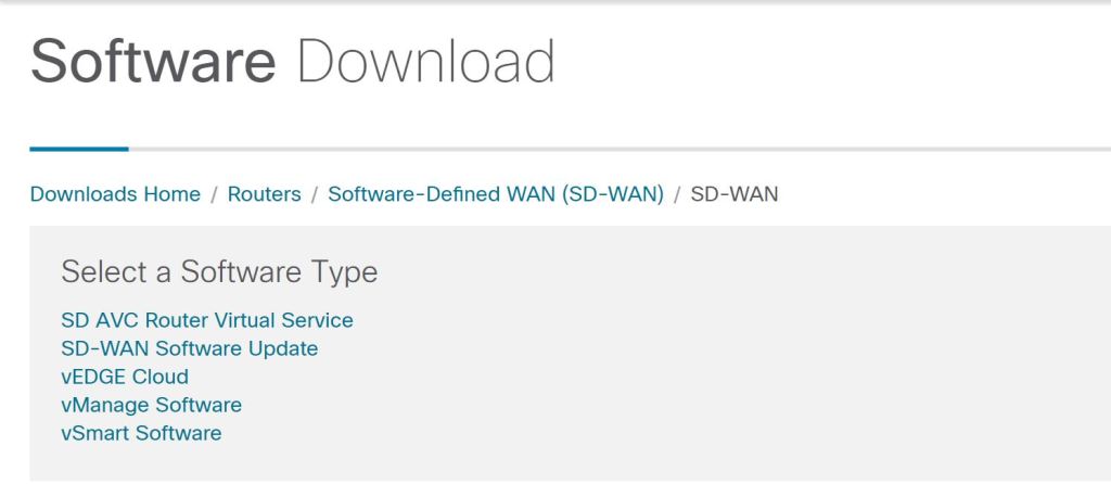
Initial install is pretty painless. In ESXi, just Create/Register VM and browse to the downloaded OVA. A couple things to point out:

  • The vBond download is listed as vEdge Cloud. This is because a vBond is just a vEdge router that’s running only the vBond services. It can not also act as a router.
  • The default username and password is admin/admin.
  • When you start up vManage, it’ll complain that there’s no HDD and shut down. You need to manually add a second drive of at least 100GB for the vManage database.
  • Kind of like ISE, there are some IOS-style commands you can run, such as show run.
vManage Initial Config

After logging in with admin/admin, you’ll be prompted to change the password. You then need to select the HDD you want to use for the vManage database.

vManage: Select storage device

Afterwards, you’re prompted for a username and password. I first tried my new vManage password, which didn’t work. So then I tried admin/admin and that did work. It turns out, this is a separate database username and password. We should update this one, too, to keep things secure. You have to stop the application-server, change the password, then start it again.

request nms application-server stop
request nms configuration-db update-admin-user
Enter current user name: admin
Enter current user password: admin
Enter new user name: admin
Enter new user password: C!sco123
request nms application-server start

Let’s configure VPN0, which is our Underlay VPN. I’m going to try to avoid overcomplicating this and not use the management VPN, VPN512, unless I have to.

config t
vpn 0
interface eth0
ip address 192.168.150.171/24

ip route 0.0.0.0/0 192.168.150.1 1
commit

(Don’t forget to commit your changes.)

Something interesting to note, you can type everything after config t all in one line, like this:

conf t
vpn 0 interface eth0 ip address 192.168.150.171/24

commit

I left the following commands off and vBond wouldn’t sync. It allowed me to add it to vManage and install certs, but just wouldn’t sync (no host-name showing, and no system-ip, etc). After adding these, it came right up.

config t
vpn 0
interface eth0
tunnel-interface
allow-service all
exit
no shutdown

Let’s also set up some base system config:

config t
system
site-id 100
system-ip 192.168.250.171

Now we can jump into the GUI and set things up. Let’s go straight to Administion > Settings. Before we can do anything with certificates, we have to set the Organization Name.

vManage: Administration > Settings

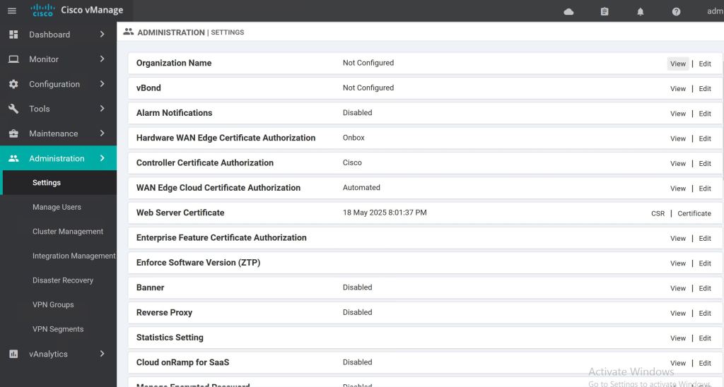
Then we should get our certs taken care of. The CA Root Cert is uploaded in the Controller Certificate Authorization section. When filling out the CSR fields, the Organization should be vIPtella Inc (no period after Inc., and the I and P are capitals). The OU field should match what you’re setting as your organization-name on each device.

vManage: Root Cert

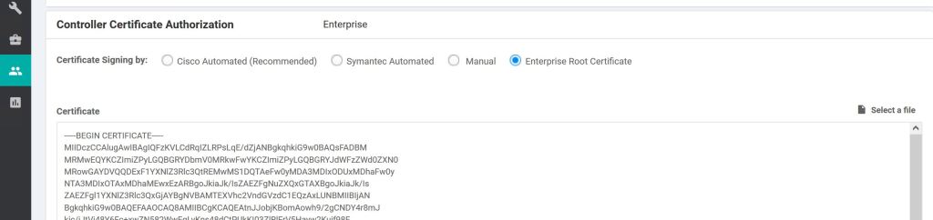
Select the Enterprise Root Certificate radio button and paste in your CA root cert, or click Select a file and upload it. Supposedly this root is supposed to be synced up to the other vNodes automatically, but I can’t find good documentation on that.
There’s also a Root-Cert-Sync URL:
https://{vmanage-ip}/dataservice/system/device/sync/rootcertchain
Check it from the CLI:
show certificate root-ca-cert

Once that is done, we want to take care of the system cert that’ll be used for authenticating our vManage to the other SD-WAN nodes. We go to Configuration > Certificates > Controllers and click the three little dots.

vManage: Configuration > Certificates

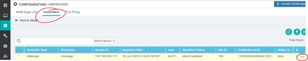
Click Generate CSR. Interestingly, you don’t get prompted to fill in any fields, the CSR fields are populated automatically by vManage. So we just need to jump over to our Windows CA, get it signed (I used a server auth & client auth template, the same one I use for pxGrid), and then come back and hit Install Certificate to upload the signed one.

A couple useful show commands on the vManage to check the status of the peer nodes:
show control ? (They’re all pretty useful, but these three are particularly good.)
show control summary
show control local-properties
show control connections

So let’s jump over to our vBond server and get it set up…

vBond

The vBond config is a bit different than the vManage config. One difference is the vBond defaults to four interfaces when you install the OVA, so you have to make sure you get your VM interface settings correct, and also configure the correct VPNs on vBond. The second thing, which is really big, is the vBond is really just an vEdge router. So we need to tell it to only be a vBond. That’s done with the vbond … local command. Also, you have to disable the VPN 0 tunnel-interface.

conf t
system
site-id 100
system-ip 192.168.250.171
vbond 192.168.150.173 local
organization-name MyOrg
vpn 0
interface ge0/0
no tunnel-interface
ip address 192.168.150.173/24
exit
ip route 0.0.0.0/0 192.168.150.1 1
commit

Installing the CA Root Cert is pretty painful. It’s supposed to be automatic with newer releases, but either I did something wrong, or it just wasn’t working (Looking back, I think it was because I hadn’t yet disabled the tunnel-interface setting on the vBond). I did find a really good how-to on manually copying it at nwktimes.blogspot.com

The way they suggested it, which worked great, was by using WINSCP to copy the root over to the /home/admin folder. Then run the following command from the CLI:
request root-cert-chain install /home/admin/my-ca-root.pem

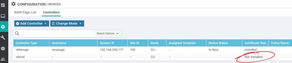
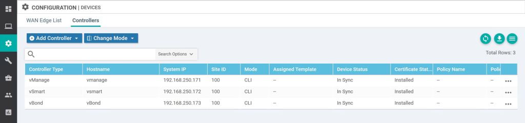
After the CA Root cert is installed, we should now be good to add the vBond into vManage under Configuration > Devices > Controllers, click Add Controller > vBond.

vManage: Add Controller vBond.

Enter the IP of the vBond, along with the username and password. Also, check the box to Generate a CSR, it’ll save a step later.

vManage: Add vBond.

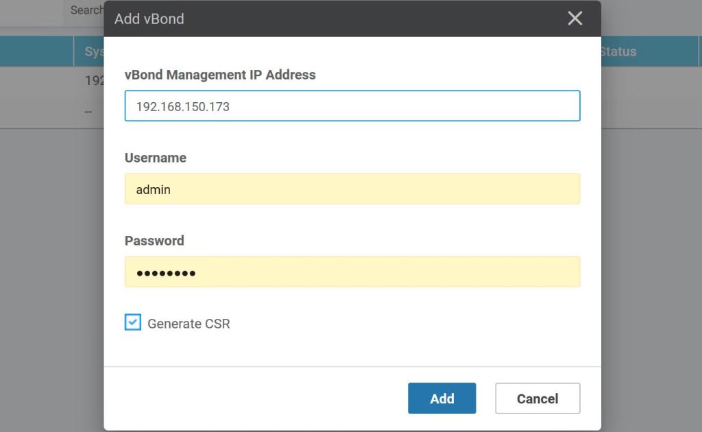
If you didn’t check the generate CSR box earlier, you can do it under Configuration > Certificates > Controllers. We don’t need to because we had checked the box when we were adding the vBond earlier.

vManage: View vBond CSR.

After getting it signed by our very own Windows Server CA, we just have to import it, same as with the vManage.

vManage: Import vBond cert.

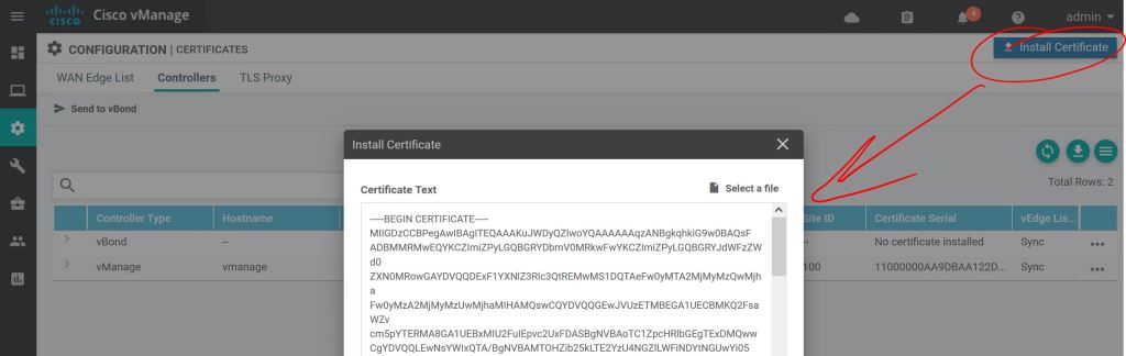
Click the little arrow to the left to see the details.

vManage: vBond cert details.

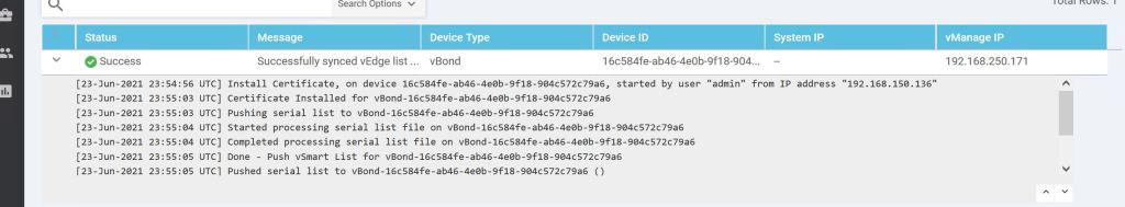
Then just rinse and repeat for vSmart. Just configure the system settings and the IP, add the root cert, join it to vManage from the Device menu, then do the system cert steps. Easy…

vManage: All three are now in sync.
What about PNP and ZTP?

If you want a dedicated PNP/ZTP server, you use the same OVA as vEdge/vBond.

3.1.b ii MP-BGP VPNv4/VPNv6

Since I covered VPNv4 pretty thoroughly in the previous post (3.1.b i), I’m going to stick to just VPNv6 here.

You basically have two options: tunnel your IPv6 traffic from your CE routers using something like GRE, or use IPv6 + Label on the PE routers. For this labbing exercise, I’m going to focus on the IPv6 + Label option. IPv6 + Label has two flavors, 6PE and 6VPE. The big difference is that 6VPE is carrying IPv6 prefixes across a VPN, completely separate from other customers using the same MPLS network.

6PE Overview
  • The PEs are running dual stack. The P routers don’t even need to support IPv6, which is cool.
  • No VPNs for IPv6, which means no VRFs for IPv6 on the PE routers. It’ll all be in the global routing table.
  • The same interface can be used for IPv4 with VRFs and IPv6.
  • A second MPLS label will be used for IPv6 prefixes. This is required, otherwise the penultimate router would need to understand IPv6 when it pops the label before sending to the egress LSR.
6PE Configuration

Super easy, we just add the send-label command.

R1:
router bgp 100
address-family ipv6
neighbor 10.4.4.4 activate
neighbor 10.4.4.4 send-label

6VPE Overview
  • Pretty similar to 6PE and MPLS VPN IPv4.
  • P routers still don’t need to know anything about IPv6.
  • PE routers must be IPv6 capable.
  • Interfaces facing CE routers have VRFs for IPv6 (and IPv4, if needed).
  • MP-BGP (or MP-iBGP, if you prefer that name) full mesh between PE routers and distributes the IPv6 VPN prefix-to-label mapping. Pretty much the same as IPv4. Now it’s called “vpnv6 + label”.
  • It is still a two label stack. MPLS/IGP is the top label, BGP label is the bottom label.
  • IPv6 between CE and PE routers.
Topology: IPv6 only between CE and PE routers.
6VPE CONFIGURATION

There are a couple things I want to note here.

  1. I’m just putting the configs for the left side of the diagram so this post isn’t a mile long. The right side can just be copied and pasted in notepad with the IPs changed.
  2. I didn’t include the MPLS config because it’s the same as previous posts. Just enable it on the P and PE router interfaces.
  3. I thought this was going to be a super simple config that I banged out in 20 minutes, but I ended up spending 4 hours on it last night trying to get it working. I didn’t follow the simple rule, “Configure things in small chunks and make sure the first chunk works before moving onto the next chunk.” I screwed up the basic EIGRP config and that cascaded to end-to-end failure. I spent the whole time chasing BGP ghosts. If this were the lab, I would’ve burned 4 hours on a 30-minute task.

R1:
vrf definition CUS_A
rd 100:500
address-family ipv6
route-target import 100:65
route-target export 100:56
! I’m using different numbers for the RT values to show how they’re related on R4. R4 will use the opposites, “import 100:56, export 100:65”
vrf definition CUS_B
rd 100:700
address-family ipv6
route-target import 100:87
route-target export 100:78

inter gig 0/0
vrf forwarding CUS_A
ipv6 address 2001:A:5::2/64
inter gig 0/2
vrf forwarding CUS_B
ipv6 address 2001:B:7::2/64
interface Loopback 0
ip add 10.1.1.1 255.255.255.255

! Important thing to note. When I was labbing this, I just couldn’t get it to work. I spent an hour triple checking my BGP config. Turned out to be the loopback 0 interfaces were not reachable between MPLS peers. I had forgotten to advertise them with EIGRP. show mpls forwarding-table was showing everything as No Label.
mpls ldp router-id loopback 0
int gig 0/1
ip address 10.12.0.1 255.255.255.0
mpls ip

! Again, we have to make sure the MPLS P routers can communicate from loopback to loopback.
router eigrp 100
network 10.1.1.1 0.0.0.0
network 10.12.0.0 0.0.0.255

router bgp 100
neighbor 10.4.4.4 remote-as 100
neighbor 10.4.4.4 update-source Loopback0

! We’ll explicitly disable the ipv4 address-family neighborship.
address-family ipv4
no neighbor 10.4.4.4 activate

! I find this to be confusing, but the VPNV6 is set up with the iBGP IPv4 addressing. But remember, the whole MPLS network is IPv4.
address-family vpnv6
neighbor 10.4.4.4 activate
neighbor 10.4.4.4 send-community extended
address-family ipv6 vrf CUS_A
redistribute connected
neighbor 2001:A:5::1 remote-as 500
neighbor 2001:A:5::1 activate
neighbor 2001:A:5::1 send-community both
address-family ipv6 vrf CUS_B
redistribute connected
neighbor 2001:B:7::1 remote-as 700
neighbor 2001:B:7::1 activate
neighbor 2001:B:7::1 send-community both

R5:
router bgp 500
bgp router-id 10.5.5.5
no bgp default ipv4-unicast
neighbor 2001:A:5::2 remote-as 100
address-family ipv6
network 2001:A:105::/64
neighbor 2001:A:5::2 activate

R7:
router bgp 700
bgp router-id 10.7.7.7
no bgp default ipv4-unicast
neighbor 2001:B:7::2 remote-as 100
address-family ipv6
network 2001:B:107::/64
neighbor 2001:B:7::2 activate


3.1.b iii Extranet (route leaking)

The focus here is setting the two customers up to be able to talk to each other. At the most basic level, we can use the Route Targets. For simplicity’s sake, I’m going to add a second loopback prefix that’s unique for each customer. Otherwise we’d need to do Twice NAT, which NATs out the source and destination IPs.

The following prefixes have been added:
Customer A – R7: 191.7.0.0/24
Customer A – R8: 191.8.0.0/24
Customer B – R9: 191.9.0.0/24
Customer B – R10: 191.10.0.0/24

R4: Customer A routes.
R4: Customer B routes.

One way we can easily share routes is to just add the Customer B route-target to the Customer A vrf. What could go wrong?

R1:
vrf definition CUS_A
address-family ipv4
route-target import 100:910

Note: 100:910 is the Customer B route distinguisher (RD) AND it’s what we used for the route-target (RT). It makes things easier, fewer numbers to remember, but it also adds confusion. What am I importing here, the RD or the RT?

R1: Route-target import 100:910
R1: RD and RT are the same value, as shown here.

The answer: it’s the RT, route-target, that we’re importing. But just to prove it, let’s change the RT to 100:9010 on R1 and R4.

R1: Updated RT for Customer B.

Now let’s check Customer A’s routing table on R1.

R1: Show ip route vrf CUS_A

Look at this mess… we’re learning those 191.9.0.0/24 and 191.10.0.0/24 routes, but we’re also learning 192.168.101.0/24 through BGP, which is a totally different network from our own 192.168.101.0/24 network.

There has to be a way to choose which routes we want to share and which ones we don’t!
Once again, route-maps come to the rescue. Let’s share JUST the 191.9.0.0/24 route from Customer B to Customer A, and JUST the 191.7.0.0/24 route from Customer A to Customer B.

R1:
access-list 7 permit 191.7.0.0 0.0.0.255

route-map LEAK_7
! Match on the access-list
match ip address 7
! We’ll make up a new RT specifically for route leaking.
set extcommunity rt 100:999

vrf definition CUS_A
address-family ipv4
! Set the export map to the route-map above.
export map LEAK_7
! import the new RT which will be coming from CUS_B.
route-target import 100:999

! Same steps again, but for 191.9.0.0/24.
access-list 9 permit 191.9.0.0 0.0.0.255

route-map LEAK_9
match ip address 9
set extcommunity rt 100:999

vrf definition CUS_B
address-family ipv4
export map LEAK_9
route-target import 100:999

Let’s check the vrf routing tables.

R1: 191.9.0.0/24 is now present in CUS_A’s table.

And a ping test from R7 to R9.

R7: Ping to 191.9.0.1 succeeds.

And a little more detail with show bgp vpnv4 unicast vrf CUS_A 191.9.0.1.

R1: Note the import path show 100:910, and the extended community RT 100:999.

So far everything looks great. There’s just one minor problem. R8 across the WAN can no longer see the 191.7.0.0/24 network, and R10 can’t see 191.9.0.0/24. So we managed to break what was already working.

R8: Routes are not gone… sad.

It’s a pretty easy fix, just modify the route-map to include RT 100:78.

3.1.b i PE-CE routing

Whatever routing protocol is running between the PE and CE will need to be redistributed into BGP, since BGP is the only protocol that supports the VPNv4 routing table. The BGP routes will also need to be redistributed into the PE/CE routing protocol.

From the PE perspective, we’ll need the VRFs set up on the interfaces and on the routing protocols. For the sake of labbing, we’ll use the same LAN subnets on both customers.

Customer A:
Loopback 101 – 192.168.101.0/24
Loobback 102 – 192.168.102.0/24

Customer B:
Loopback 101 – 192.168.101.0/24
Loobback 102 – 192.168.102.0/24

MP-BGP MPLS Topology

The config sequence will be:

  1. Configure CE routers:
    1. Loopbacks to represent local segments.
    2. Interface Gig0/0
    3. Routing protocol
  2. Configure MPLS Unicast Routing
    1. EIGRP on MPLS core.
    2. Enable MPLS globally and on interfaces.
  3. Configure PE routers:
    1. VRF config.
    2. Outside interface config: VRF and routing protocols.
    3. MP-BGP config.
CE Router Config

R7:
inter loo 101
ip add 192.168.101.1 255.255.255.0
router ospf 7
network 10.17.0.0 0.0.0.255 area 0
network 192.168.101.0 0.0.0.255 area 1

R8:
inter loo 102
ip add 192.168.102.1 255.255.255.0
router ospf 8
network 10.48.0.0 0.0.0.255 area 0
network 192.168.102.0 0.0.0.255 area 2

R9:
inter loo 101
ip add 192.168.101.1 255.255.255.0

router eigrp 9
network 10.19.0.0 0.0.0.255
network 192.168.101.0 0.0.0.255

R10:
inter loo 102
ip add 192.168.102.1 255.255.255.0

router eigrp 10
network 10.40.0.0 0.0.0.255
network 192.168.102.0 0.0.0.255

MPLS Unicast Routing Config

For details on this config, check the MPLS Operations post.

PE Router Config

Up until this point, it’s just been basic config. The PE routers will take a little more thought. I’ll put comments in line so I can remember what I’m doing.

R1:
! Define our VRFs. This should be easy, and can be copied to both PE routers without changing.
vrf definition CUS_A
! We need the route distinguisher to uniquely identify prefixes inside the MPLS business.
rd 100:78
address-family ipv4

! We need these extended community attributes in BGP to translate from the unique VPNv4 prefix, 100:78:192.168.101.1, to the IPv4 prefix, 192.168.101.1, for BGP.
route-target export 100:78
route-target import 100:78


vrf definition CUS_B
rd 100:910
address-family ipv4
route-target export 100:910
route-target import 100:910

! Set up vrf forwarding on the interfaces facing the CE routers. Remember, these are not MPLS interfaces. Again, nothing too terrible here, just standard VRF config.
interface gig0/1
vrf forwarding CUS_A
ip add 10.17.0.1 255.255.255.0
interface gig 0/3
vrf forwarding CUS_B
ip add 10.19.0.1 255.255.255.0

! Set up the routing protocols. The redistribution is the only thing to be careful about until we get to the BGP setion.
router ospf 7 vrf CUS_A
network 10.17.0.0 0.0.0.255 area 0
redistribute bgp 100


router eigrp CUS_B
address-family ipv4 unicast vrf CUS_B autonomous-system 9

! It took me a minute to find the redistribute command. It’s under the topology subsection.
topology base
! Don’t forget, for redistributing into EIGRP you have to include the metric info.
redistribute bgp 100 metric 100 1 255 1 1500

router bgp 100
neighbor 10.4.4.4 remote-as 100
neighbor 10.4.4.4 update-source loopback 0

! This next command is the key to setting up the VPNv4 routing.
address-family vpnv4
neighbor 10.4.4.4 activate
address-family ipv4 vrf CUS_A
redistribute ospf 7
address-family ipv4 vrf CUS_B
redistribute eigrp 9

All in all, this isn’t too bad. A lot of basic config for routing and vrfs. The MPLS part is pretty simple, just the ldp router-id and then enabling it on the interfaces. Then the big twist at the end is just doing the activate command under bgp address-family vpnv4. When you break it down into parts, it’s easy stuff.

But how does it work?

How are all of these components working together? We’ll need to follow the path of the packet through the network to see it in action. Let’s follow a ping from Customer A’s 192.168.101.1 (R7 Loopback 101) to Customer A’s 192.168.102.1 (R8 Loopback 102).

First let’s confirm that a ping will actually succeed.

R7: Sanity check. Ping is successful.

Now let’s see the details with a traceroute. We can see that we’ve got some MPLS going on there. Also, 10.48.0.8 is interface gig 0/0 on R8.

R7: Traceroute successful. We’ll want to take note of these MPLS Labels.

The first hop is pretty straightforward. It’s just an OSPF route learned from R1. It’s an E2 route because it’s coming from a different area, Area 0.

R7: Route to 192.168.102.1 learned from OSPF.

Hopping over to R1, we know we can’t just do a show ip route, because the only thing in the global routing table will be those EIGRP 100 routes, plus the connected routes. A show ip route vrf CUS_A should get us started.

R1: Show ip route vrf CUS_A.

So we learned from BGP that to get to 192.168.102.1, we’ll need to take 10.4.4.4. The only problem is, how do we get to 10.4.4.4? There’s no route here for that! Luckily we have MPLS configured. Let’s do a show mpls forwarding-table.

R1: MPLS table.

We know from our traceroute that the packet went to 10.12.0.2 next. We can also see the labels listed as 19/21. Label 19 makes sense, as this table above shows 10.4.4.4/32 with Outgoing Label 19, and a next hop of 10.12.0.2. Where does 21 come into play? Let’s check the MPLS table on R2.

R2: MPLS table.

We see here that R2 needs to swap the label 19 (Local Label) for 19 (Remote Label). Again, it’s ok that they use the same label. But the swap still has to happen. The question still remains, where the hell is this mystery 21 label? We see it again on the 3rd hop of the original traceroute, 19/21. It’s almost like there’s a 21 getting stacked in there… Let’s check R3.

R3: MPLS table.

R3 knows how to get to 10.4.4.4 via 10.34.0.4, but it also knows to pop the label before sending, since R4 is the egress LSR. Still no label 21 though! Let’s take a look at R4.

R4: Show ip cef.

With a show ip cef we can finally understand the mystery of that 19/21 label stack in the traceroute. This whole bit probably belongs under the MPLS Traceroute section, but it’s still relevant here.

There’s another missing piece here. We know how MPLS works with the label swapping, but what we’re not seeing is how R4 knows which VRF to route the packet through. The MPLS traffic is coming to R4 on a global interface, Gig 0/0. And we know that R4 has two customers with 192.168.102.1 IP addresses, so how can R4 figure out which one to use?

The solution is to add another label to the MPLS stack. The top label is the regular MPLS label for getting from one PE to the other. The bottom label (usually) tells the egress PE what the next hop should be. The PE can figure it out from there which VRF that should be.

The top label is distributed by LDP from neighbor to neighbor, swapped or popped accordingly. The bottom label (the VPN label) is shared from PE to PE using MP-BGP.

3.1 MPLS: 3.1.a Operations

There’s a delicate balance in labbing and studying. During your time spent labbing topic X, your knowledge of topics Y and Z are slowly draining out. When I was studying for the CCIE Security exam, I feel like I spent too much time (about a month straight) working on FLEXVPN. By the time I felt like I had a really good handle on it, I realized I had regressed quite a bit on every other topic. I wasn’t balance in my approach.

This brings me to MPLS. According to the blueprint, MPLS and DMVPN combined make up just 15% of the exam. (MPLS is a huge topic on the CCIE Service Provider exam, spanning multiple sections.) So the trick for the Enterprise Infrastructure lab will be determining how much time and effort I put into learning the nuts and bolts of MPLS. At the moment, my knowledge is about a 1 out of 5. I understand the how and why at a pretty basic level, but I definitely need to sharpen up. So let’s take a look at labminutes.com and see what kind of MPLS offerings they have:

Labminutes.com – The best site ever.

Ouch. First, notice MPLS doesn’t even sit under the R/S section, it’s under Service Provider. And there are 61 videos, averaging 20 minutes each, so probably in the 20 hour ballpark. How far can you afford to go down that rabbit hole? Sadly, the answer is “All the way.” We just have to bite the bullet and learn it all. If we learn it inside and out then it probably will barely show up on the lab. But if we learn it half-assed, then it’ll most likely be a huge chunk right at the center of the exam, and if you can’t get it working everything around it falls apart.

The key is to have a steady labbing schedule where you constantly review the things you’re pretty comfortable with while continuing to dive into things that you suck at.

So let’s get started:

I’m going to rely on three sources:

  1. As always, LabMinutes – Video: Service Provider | Lab Minutes
  2. MPLS in the SDN Era –
  3. MPLS Fundamentals –

Why MPLS?
According to MPLS Fundamentals, it’s no longer about faster switching since the hardware has advanced to a point where there’s no real gain from the faster lookup of 20-bit labels as opposed to full 32-bit routes. So let’s look at the real reasons:

  • The use of one unified network infrastructure.
  • Better IP over ATM integration.
  • Border Gateway Protocol (BGP)-free core.
  • The peer-to-peer model for MPLS VPN.
  • Optimal traffic flow.
  • Traffic engineering.

MPLS Fundamentals breaks all these down in a lot of detail. But for right now, I want to focus on the third one, BGP-free Core.

Let’s take a look at the topology we’ll be labbing with:

MPLS Topology

The idea is that AS 100 is a transit AS between AS 700 and AS 800. There’s no direct link between R1 and R4, there’s just the logical iBGP neighborship. So we have a little bit of a problem here.

We want to get traffic between 10.7.0.1 in AS 700 to 10.8.0.1 in AS 800.
Let’s check R7’s BGP table:

R7: Seems there’s a known path to the 10.8.0.0/24 network.

Let’s try a traceroute:

R7: Traceroute fails after hitting R1.

So let’s figure out why this is failing. We’ll start by verifying that R1 knows the way to 10.8.0.1.

R1: Seems to know how to get to 10.8.0.0/24

Looks good from R1’s perspective:
R1 learned from BGP to take 10.48.0.8 to get to 10.8.0.1.
To get to 10.48.0.8, take 10.4.4.4, which was also learned through BGP.
To get to 10.4.4.4, take 10.16.0.6 or 10.12.0.2, which R1 learned from EIGRP.

So then let’s check 10.12.0.2:

R2: Uh-oh. Not enough routing information here.

Looks like R2 has no idea how to get to the 10.8.0.0/24 network, or the 10.7.0.0/24 network.

What we have here is a failure to communicate. What are our options then?

  • We could run iBGP on all of the routers in the core of AS 100, but we don’t want to overload all those guys in the middle with these potentially huge routing tables. Plus we’d have to do a full mesh, or set up some route-reflectors.
  • We could redistribute our routes between EIGRP and BGP, but of course we don’t want to lose our BGP attributes, so that’s not a good option.
  • What about this MPLS business? With MPLS, the EIGRP routers don’t really need to know where 10.8.0.0 and 10.7.0.0 are. They just need to look at their local label and the remote label of the directly connected neighbor. The actual source and destination IPs in that packet don’t matter.

MPLS Configuration

The good news is, the basic configuration is pretty easy and straightforward.
R1:
(Make sure your loopbacks are reachable by your neighbor)
mpls ldp router-id loopback 1
(Configure on the interfaces where your EIGRP 100 neighbors are hanging out.)
interface gig0/1
mpls ip
interface gig 0/2
mpls ip

A note about speed and the ticking of the clock during the exam. The clock is your biggest enemy. On my first attempt at the CCIE Security lab, I felt like if I had about 18 or 24 hours to complete it, I could’ve passed. I felt like I could’ve figured out and configured most of the tasks if I had unlimited time. But that 8-hour clock is killer. After that trouncing, I began to lab for speed. Key changes I made to my game plan were cutting out unnecessary keystrokes and breaking the habit of hitting the tab key. (The other big one was using notepad and copying/pasting configs from there.) Every second counts. So when you’re configuring MPLS on an interface it should be more like this:
R1:
mp ld r loo1
in gi0/0
mp i

So after slapping on that super-easy config, let’s try a ping:

R7: Ping 10.8.0.1 works!

3.1.a i Label stack, LSR, LSP

For the sake of completeness, I want to just touch on each of the subsections under 3.1.a.

  • Label Stack:
    • Basically, LSRs (which we’ll learn about in a minute) might need more than one label stacked on top of each other.
    • From a packet perspective, they’re in sequence after the L2 header and before the L3 header.
    • In short, you can have multiple labels nested (unlike TrustSec cts tags, which is one and only one.)
    • You know you got to the bottom of the stack when the BoS bit is set to 1.
  • LSR:
    • A Label Switching Router. In our diagram, these are R1 through R6.
    • Three types exist, but the only difference is which interfaces have MPLS configured.
      • Ingress LSR: Gets the unlabeled packet on the way in and applies a label.
      • Intermediate LSR: Switches labeled packets in one interface and out the other, swapping out the label each time.
      • Egress LSR: Takes the label off and shoots it out the exit interface.
  • LSP:
    • Label Switching Path.
    • Basically the path through the MPLS domain. In our case it would be R1-R2-R3-R4 or R1-R6-R5-R4.

3.1.a ii LDP

You need a method of distributing these labels around your network. The only real options would be modifying routing protocols to carry that burden, or come up with a separate Label Distribution Protocol. MPLS Fundamentals talks a bit about this, but the short answer is that the only routing protocol that really handles label distribution is BGP (which is not an IGP, of course) for MPLS VPN networks. That’s why we need LDP running. The basics of how it works:

  • LSRs distribute the label-to-prefix bindings to their neighbors.
  • These received bindings are what we see as “Outgoing Labels” with the show mpls forwarding-table command.
  • The LSR has to pick just one remote binding for a prefix. This is done using the regular RIB.
  • LFIB is used for the forwarding of the labeled packets.
  • The full list of bindings is the LIB. The LFIB is just one of those entries that’s used for forwarding.

3.1.a iii MPLS ping, MPLS traceroute

Traceroute in MPLS network

The big takeaway is that MPLS traceroute doesn’t work like regular traceroute. The ingress LSR (R1) sends the ICMP message with the TTL of 1 to the first intermediate LSR (R2), similar to regular traceroute, but from there it’s a totally different story. That first intermediate LSR (R2) buffers out the label stack and sends it all the way to the end of the MPLS domain (R4) with a source IP of his own interface that connects to the ingress LSR (R1) and a destination IP of the ingress LSR (R1). It’s pretty wonky.

R1: Traceroute

For the above screen cap, I had shut down the link to R6 to keeps things simple.
One thing to note, MPLS labels are locally significant. So each LSR can use the same number to mean a different thing. Not that Label 18 shows up twice. This doesn’t mean the label isn’t swapped out. Let’s look at the mpls tables.

R1: Note the outgoing label to get to 10.4.4.4 via 10.12.0.2 is 18.
R2: Notice that the local label and outgoing labels for 10.4.4.4 are both 18. It’s just coincidence and totally allowed.
R3: Remember that R3 knows the 10.4.4.4 is directly connected to R4, so it pops the label before sending.

For contrast, let’s check the other path that goes through R6 and R5:

R6: Notice that the local and outgoing labels are different on this path.
R5: Again, R5 knows that 10.4.4.4 is connected to R4, so it pops the label.

Blueprint 1.5 BGP: 1.5.b Path Selection

1.5.b i: Attributes

There are a million resources out there that will explain BGP attributes and path selection better than I can, but I’m doing this for my own purposes and will try to phrase it so I’m able to easily remember it when I come back to review. I recommend you skip this entry and check out the TCP/IP, Volume II book instead.

One thing to note that’s been making me insane regarding the amazing TCP/IP books. TCP/IP Volume 1 uses the number one, the digit. Then Volume 2 uses the Roman numeral II. The inconsistency makes me nuts. It’s like if Empire Strikes back was Episode V and Return of the Jedi was Episode 6.

So the first four are easy. Just do show ip bgp and they’re listed right there just not in order:
Weight, Local Preference, Originating Locally, AS Path, Origin Code, Metric (MED)
This order kind of makes sense.

  1. Weight: It’s Cisco proprietary, so of course it’s better than everything else. Also, it’s locally significant only to the router where it’s configured and isn’t sent in updates, so you don’t have to worry about it not being accepted by non-Cisco neighbors.
    • Default is 0.
    • Higher is better.
  2. Local Preference: This has to come second because it’s how you want to control routing in your local AS. If R2 and R3 are in AS 123 and are both directly connected to AS 500, you want to be able to decide which path your traffic takes. You can’t just use weight, because your iBGP neighbor, R1, that connects to R2 and R3 needs to know who is the preferred path. Set local preference higher on R2 for routes going to AS 500 and R2 will be sure to let R1 know, “I’m the guy, AS 500 likes me better. R3 sucks.”
    • Default is 100, but if it’s blank that means 100.
    • Higher is better.
  3. Originating Locally: This one is tough to spot in the picture. You have to look for what’s NOT there. There’s no AS_PATH listed. And I know I didn’t modify that weight manually, it must be a locally originated route. Locally originated just means it was added under the router bgp 123 section, with the network, aggregate-address, or redistribute commands. Again, it makes sense that this would be preferred over one with an AS_PATH. It’s configured locally, if we can’t trust that route, what can we trust?!
  4. AS_PATH: Shortest wins. “Who cares if it’s a 56k modem, it’s only one AS away! That 100Gig link is two AS paths away! I prefer the shorter path!”
  5. Origin Code: This is just the i at the end of the line: i beats e beats ?. (I means we used the network command. E isn’t used any more. ? means it’s redistributed into BGP)
  6. Metric (MED): This is the most confusing one. So far, everything else on the list was something that was happening locally. The MED is something we receive from a neighbor. The neighbor sends it with the BGP updates and says, “Hey, by the way, I’d prefer you send to me via R3.”
    • Lower is better.
    • Of course it has to be different. It can’t just be “higher is better” like everyone else.

The rest of the list sucks. It’s so long that it makes remembering those important ones at the top a lot harder. It’s just a bunch of tie-breaker nonsense. In short: eBGP over iBGP (quickest way out of the AS is the best), lowest IGP metrics, oldest route, lowest router-id, lowest ip address. Worry about these for written exams, but I can’t imagine them coming into play in the lab.

Configuring Path Selection

Same old topology, still. For this part we’re going to focus mostly on R3 and R2.

Local Preference
Let’s start with Local Preference. Super easy. Just a route-map:
R3:
route-map SET_LOCALPREF
set local-preference 150
router bgp 123
neighbor 10.35.0.5 route-map SET_LOCALPREF in

The trickiest thing to remember here is that we’re setting it locally in our AS, so we need to set it coming IN from the remote AS.

Below we see R3 has the LocPrf of 150 set for the paths from AS 500. But of course it does, we manually configured that value on R3. This isn’t where Local Preference shows its value.

R3: Local Preference is set to 150

Let’s look at R2 now. We didn’t configure any Local Preference on R2.

R2: We see the local preference has been modified.

Since the Local Preference is now higher on R2, which path will R2 take to get to the directly connected neighbor R5 in AS 500? Ideally, we’d want to go direct via 10.25.0.5… let’s do a traceroute and see:

R2: Traceroute to 10.5.0.1 through R3

WEIGHT
We see that R2 is taking a less optimal path now, bouncing around inside AS 123 like a pinball before going out to AS 500. How can we fix that? We don’t want to remove Local Preference from R3, because we want everyone else in AS 123 to use R3 to get to AS 500. Do we know of a way to change just the local router’s path preference? Go ahead and think about it, I’ll weight.

R2:
route-map SET_WEIGHT
set weight 25
router bgp 123
neighbor 10.25.0.5 route-map SET_WEIGHT in

Again, we’re setting up how we want to handle traffic that we learned from AS 500. In fact, it’s internally significant information, we set the weight as the insightful information is coming IN.

R2: Weight set to 25 for AS 500 neighbor.

Let’s do another traceroute.

R2: Traceroute direct, no connecting flights, no layovers!

AS-PATH
AS-Path is cool because it affects both inbound and outbound path selection, whereas Local Preference and Weight only affect outbound (the path you want to take to leave your AS) and MED only affects inbound (the path you want your neighbor to take to get to you). But it can also be tricky and dangerous. Changes to AS-Path will get propagated beyond just your local AS and your directly connected neighbors.

The config is pretty simple. The only trick is that you configure it on the router that you don’t want to be your primary router. If we want R2 to be the preferred path, we’ll configure R3 to add more AS-Paths.

R3:
route-map SET_ASPATH_IN
set as-path prepend 500 500
router bgp 123
neighbor 10.35.0.5 route-map SET_ASPATH_IN in

Just like Weight and Local Preference, we’re setting it inbound from the neighbor AS 500 because we want to affect how our local AS sends traffic out to AS 500. Typical backwards logic.

R3: Note the AS Path to 10.5.0.0/25 is now 500 500 500 through the directly connected neighbor R5.

But let’s check R5’s perspective. Since we set the as-path prepend inbound from AS 500, notice the 10.3.0.0 network still shows a single AS 123.

R5: No change in AS Path for 10.3.0.0/24 network.

Let’s set the route-map going out to 10.35.0.5 and see what happens.
R3:
route-map SET_ASPATH_OUT
set as-path prepend 123 123 123
router bgp 123
neighbor 10.35.0.5 route-map SET_ASPATH_OUT out

R5: Note the excessive 123’s in the AS Path

So that’s more like it. Notice that we see three sets of AS 123, even though we only prepended two sets in the route map. It’s because there’s the regular AS_PATH attribute that comes with the route advertisement, plus the two prepended ones.

If we didn’t set inbound and outbound AS_Path prepending, we could end up with asymmetric routing.

Metric (MED)
We’re going to use MED to tell our neighbor which route we want them to use to get to our AS. Since MED is pretty far down the list, it’ll only work if the neighbor hasn’t already modified their Local Preference or Weight (or AS_Path). You can use MED in conjunction with Local Preference to avoid asymmetric routing.

  • Lower is better.
  • Default value is zero. So by default, all MEDs are at the max value of zero.
  • Since you want to affect routes coming INTO your AS, you need to apply it OUT to your neighbor. Again, more backwards logic.
  • Like AS_Path, you can’t make yourself any better, so you need to sabotage the other routers to make them worse. Real classy…

R2:
route-map SET_MED
set metric 37
router bgp 123
neighbor 10.25.0.5 route-map SET_MED out

Again, we’re sending the modified update OUT to R5 so that he can apply it to traffic coming into our AS. I’m starting to detect a pattern with these configs…

Blueprint 1.5 BGP: 1.5.e ii Aggregation, as-set

A quick run through on route summarization with BGP.
Resources:
Video: Routing & Switching – BGP | Lab Minutes

AGGREGATION

The CIDR Report: See what a difference aggregation can make.
https://bgp.potaroo.net

What’s the difference between aggregation and summarization? It seems like we’re just doing summarization here!
According to TCP/IP, Volume II, they’re the same thing. They used to be slightly different, but not anymore. Apparently, the cool way to say it is “aggregate”. So don’t say “summary” unless you want everyone to laugh at you.

Same BGP Topology every day…

The trick with route summarization in BGP is that enabling summarization doesn’t stop the individual routes that are subsets of that summary from being advertised.
For example, if you summarize:
10.1.0.0/24
10.1.1.0/24
10.1.2.0/24
10.1.3.0/24
Summarized as:
10.1.0.0/22
You’ll end up advertising all 4 original routes, plus the summary route.

Let’s see it in action…
R1
router bgp 123
aggregate-address 10.1.0.0 255.255.252.0

R1: Aggregate-address command
R2: The original /24 routes, plus the additional aggregate route.

How do we deal with this nonsense!?
You can just use summary-only to advertise just that summary route.

R1: Aggregate-address command with summary-only
R2: show ip bgp command now displays only the summary route.

That seems simple enough. But you can’t pick and choose where you want to advertise the summary route vs. where you want to send the individual routes.
Let’s get rid of this summary-only command and switch to prefix lists, instead. Then we have more control.

Task 1: Send 10.1.0.0/22 summary route to R7. Send the individual routes to R2 and R3. Do not send the summary route to R2 and R3.

R1:
!Create a prefix-list that blocks the 10.1.0.0/22 routes with a
! subnet greater than or equal to /24
ip prefix-list SEND_SUMMARY deny 10.1.0.0/22 ge 24
ip prefix-list SEND_SUMMARY permit 0.0.0.0/0 le 32
!Create a prefix-list that blocks only the summary route.
! The individual routes get sent. Leaving off le or ge means an implicit =mask

ip prefix-list BLOCK_SUMMARY deny 10.1.0.0/22
ip prefix-list BLOCK_SUMMARY permit 0.0.0.0/0 le 32
router bgp 123
neighbor 10.17.0.7 prefix-list SEND_SUMMARY out
neighbor 10.12.0.2 prefix-list BLOCK_SUMMARY out
neighbor 10.13.0.3 prefix-list BLOCK_SUMMARY out

R7: After prefix-list applied. Summary route only appears.
R2: Only the individual routes are showing up.
R3: Same thing here, just the individual routes.

But wait! There’s more.
What if I want to keep things simple by using the summary-only command. But then I decide I also want to send the 10.1.2.0/24 to R7?
We can leak it with a route-map using the unsuppress-map command!

First thing, we clear out all the previous config on R1. Then we apply:
router bgp 123

aggregate-address 10.1.0.0 255.255.252.0 summary-only

Verify on R2 that we’re only getting the summary route:
show ip bgp

R2: Summary route 10.1.0.0/22 only.

TASK 2: Summarize the 10.1.0.0/24 through 10.1.3.0/24 networks. Only send the summary route to R7 and R3. Send the summary route and route 10.1.2.0/24 to R2.
R1:
ip prefix-list PL_LEAK permit 10.1.2.0/24
!Create the route-map
route-map RM_LEAK
match ip address prefix PL_LEAK
router bgp 123
neighbor 10.12.0.2 unsuppress-map RM_LEAK

R2: Unsuppress-map applied.

OK, so that’s great. But what about the suppress-map option under the aggregate-address command, what does that do?

R1: Aggregate-address options

We can use suppress-map to send the summary, but also filter out some of the individual routes. This is similar to what we did with Task 2, but it affects all neighbors. Let’s try to suppress 10.1.0.0/24, 10.1.1.0/24, and 10.1.3.0/24. The end result should be that we’re advertising the summary route, 10.1.0.0/22, plus the 10.1.2.0/24 route only.

We have two options for the prefix-list:

First is to permit all of the routes that exist in the aggregate range that we want to suppress:
ip prefix-list PL_LEAK1 permit 10.1.0.0/24
ip prefix-list PL_LEAK1 permit 10.1.1.0/24
ip prefix-list PL_LEAK1 permit 10.1.3.0/24
(implicit deny at the end)

Second is to deny the one route that we want to leak, and permit everything else. This is one of those backward logic scenarios where permit and deny appear to be reversed. Permit means, “Which routes do we want to suppress, i.e. NOT advertise.”
ip prefix-list PL_LEAK1 deny 10.1.2.0/24
ip prefix-list PL_LEAK1 permit 0.0.0.0/0 le 32

route-map RM_LEAK1
match ip address prefix PL_LEAK1

router bgp 123
aggregate-address 10.1.0.0 255.255.252.0 supress-map RM_LEAK1

AS-SET

One of the shortcomings with aggregation is that we lose the AS-Path, which we know we need for loop prevention. Let’s take a look at some route aggregation for R7:
10.7.0.0/24
10.7.1.0/24
10.7.2.0/24
10.7.3.0/24

Aggregated as 10.7.0.0/22

R7 Routes need to be aggregated as 10.7.0.0/22.

Let’s see what happens on R4 if we use aggregate-address on R7:

R4: Path originates from AS 700

But what if R1 in AS 123 does the aggregation?

R4: uh-oh… looks like AS 123 is taking all the credit.

This looks like a recipe for a routing loop. Let’s see what R7 thinks about all of this:

R7: Again, AS 123 is taking credit for the 10.7.0.0/22 route.

If 10.7.3.1 on R7 goes down, the traffic won’t actually loop, but R7 will try to send it to R1. R1, as the aggregator, will just drop it because it won’t have a more specific route.
Is there any way for R4 to know this aggregation is happening?

R4: Note the “atomic-aggregate” attribute.

This brings us to the as-set command. This will tell the aggregator to include an unordered AS list. So in our case, R1 should include AS 700 in it’s path attributes.
R1:
router bgp 123
aggregate-address 10.7.0.0 255.255.252.0 summary-only as-set

R4: AS 700 is back in the path!
R4: The atomic-aggregate attribute is gone. But we still have the “aggregated by” note.

Blueprint 1.5 BGP: 1.5.c iii Outbound Route Filtering

1.5.c iii Outbound Route Filtering

I’m doing some brief route filtering labbing today. The resources I’m using are:
LabMinutes.com
Video: Routing & Switching – BGP | Lab Minutes

labminutes.com

Routing TCP/IP, Volume II: CCIE Professional Development, Second Edition
https://learning.oreilly.com/library/view/routing-tcpip-volume/9780134192772/

From the section: Filtering Routes by NLRI (Network Layer Reachability Information)

“IOS provides two tools for per-NLRI route filtering: Distribute lists and prefix lists. Prefix lists are the more recent and the more preferred tool; their configuration variables make them more versatile, and they can have less performance impact on the router.” (Doyle, 2016)

So let’s attempt the following tasks:
1. Use a prefix-list to filter out the 10.70.0.0/24 network from being advertised to AS 400 and AS 500 from R2
2. Filter out the 10.70.0.0/24 network from being advertised to AS 500 and AS 600 from R3, do not user prefix-lists.
3. Use AS-Path Filtering to prevent AS 123 from being used as a transit AS between AS 400 and AS 500.

Basic topology

Task 1: Use a prefix-list to filter out the 10.70.0.0/24 network from being advertised to AS 400 and AS 500 from R2.

For this task we’ll use prefix-lists.
First, let’s verify on R4 that route 10.70.0.0/24 exists.
show ip bgp
or
show ip bgp 10.70.0.0/24 subnets

R4: 10.70.0.0/24 learned from R2 and R5.
R5: 10.70.0.0/24 learned from R2, R3, R4, and R6

R2
ip prefix-list PLIST-70 deny 10.70.0.0/24
ip prefix-list PLIST-70 permit 0.0.0.0/0 le 32
router bgp 123
neighbor 10.24.0.4 prefix-list PLIST-70 out
neighbor 10.25.0.5 prefix-list PLIST-70 out

R4: 10.70.0.0/24 is now only being learned from R5.
R5: 10.70.0.0/24 is now only learned from R3 and R6.
R2: show ip prefix-list detail

Task 2: Filter out the 10.70.0.0/24 network from being advertised to AS 500 and AS 600 from R3, do not user prefix-lists.

For this task we’ll use good old-fashioned ACLs and distribute-lists.
We already verified what we’re seeing on R4 and R5 with the previous task, but let’s check R6.

R6: 10.70.0.0/24 is learned from R3 and R5.

R3
access-list 70 deny 10.70.0.0 0.0.0.255
access-list 70 permit any
router bgp 123
neighbor 10.35.0.5 distribute-list 70 out
neighbor 10.36.0.6 distribute-list 70 out

R4: 10.70.0.0/24 is successfully filtered out.
R5: 10.70.0.0/24 is successfully filtered out.
R6: 10.70.0.0/24 is successfully filtered out.

Task 3: Use AS-Path Filtering to prevent AS 123 from being used as a transit AS between AS 400 and AS 500.

So this scenario could be that our main customer site is AS 123. AS 400, AS 500 are our ISPs and we don’t want them to use our customer site as a transit. The way it’s configured now, if the link between R 4 and R5 goes down, R4 will just route traffic through AS 123 to get to R5.
Let’s verify this on R4:
show ip bgp 10.50.0.0/24 subnets

R4: Verify path to 10.50.0.0/24 through AS 123.

And on R5:
show ip bgp 10.40.0.0/24 subnets

R5: Verify path to 10.40.0.0/24 through AS 123.

Apply AS-Path filtering:
R2
ip as-path access-list 4 deny _400_
ip as-path access-list 4 permit .*
ip as-path access-list 5 deny _500_
ip as-path access-list 5 permit .*
router bgp 123
neighbor 10.24.0.4 filter-list 5 out
neighbor 10.25.0.5 filter-list 4 out

R4: AS Path Filter seems to work. The only path to 10.50.0.0/24 is direct to R5.
R5: Looks like we can still get to AS 400 through AS 123 as learned from R3.

Let’s filter out the path from R3 to R5:
R3
ip as-path access-list 4 deny _400_
ip as-path access-list 4 permit .*
router bgp 123
neighbor 10.35.0.5 filter-list 4 out

R5: AS Path Filtering appears to be successful…

Let’s do one final test, though. What happens if we kill the link between R4 and R5?
R5
interface gig 0/2
shutdown

R5: R5 will still pass through AS 123 to get to 10.40.0.0/24, it’ll go via 600 to R3.

So how can we make this work?
If we control R6, we can add AS-Path Filtering there to prevent AS 400 from being advertised to R5. If not, then we’ll need to also filter routes going out to R6.

Base Config:
R1 (AS 123 Router Reflector)
router bgp 123
bgp log-neighbor-changes
network 10.12.0.0 mask 255.255.255.0
network 10.13.0.0 mask 255.255.255.0
network 10.17.0.0 mask 255.255.255.0
neighbor 10.17.0.7 remote-as 700
bgp cluster-id 123
neighbor 10.12.0.2 remote-as 123
neighbor 10.12.0.2 route-reflector-client
neighbor 10.13.0.3 remote-as 123
neighbor 10.13.0.3 route-reflector-client

R2
router bgp 123
bgp log-neighbor-changes
network 10.12.0.0 mask 255.255.255.0
network 10.23.0.0 mask 255.255.255.0
network 10.24.0.0 mask 255.255.255.0
network 10.25.0.0 mask 255.255.255.0
neighbor 10.12.0.1 remote-as 123
neighbor 10.24.0.4 remote-as 400
neighbor 10.25.0.5 remote-as 500

R3
router bgp 123
bgp log-neighbor-changes
network 10.13.0.0 mask 255.255.255.0
network 10.23.0.0 mask 255.255.255.0
network 10.35.0.0 mask 255.255.255.0
network 10.36.0.0 mask 255.255.255.0
neighbor 10.13.0.1 remote-as 123
neighbor 10.35.0.5 remote-as 500
neighbor 10.36.0.6 remote-as 600

R4
router bgp 400
network 10.24.0.0 mask 255.255.255.0
network 10.45.0.0 mask 255.255.255.0
neighbor 10.24.0.2 remote-as 123
neighbor 10.45.0.5 remote-as 500

R5
router bgp 500
network 10.25.0.0 mask 255.255.255.0
network 10.35.0.0 mask 255.255.255.0
network 10.45.0.0 mask 255.255.255.0
network 10.56.0.0 mask 255.255.255.0
neighbor 10.25.0.2 remote-as 123
neighbor 10.35.0.3 remote-as 123
neighbor 10.45.0.4 remote-as 400
neighbor 10.56.0.6 remote-as 600

R6
router bgp 600
network 10.36.0.0 mask 255.255.255.0
network 10.56.0.0 mask 255.255.255.0
neighbor 10.36.0.3 remote-as 123
neighbor 10.56.0.5 remote-as 500

R7
router bgp 700
network 10.17.0.0 mask 255.255.255.0
network 10.70.0.0 mask 255.255.255.0
neighbor 10.17.0.1 remote-as 123

The Journey to CCIE Enterprise Infrastructure

This is my first attempt at blogging. The goal is to document my CCIE Enterprise Infrastructure journey, including detailed labs and configs and whatever else comes up. There are a couple reasons I decided to document my studies as a blog:

  • I’m hoping that this may help others who are also on the journey. It seems that there are not a ton of resources out there for the CCIE Ent. Inf. exam, probably because it’s still relatively new (as of June, 2021).
  • I may end up with some one-off lab examples that are useful to people who don’t care about CCIE exams at all.
  • Most importantly, I figure this is a good way of holding myself accountable and staying on task.

First thing’s first, I’ll be working through this blueprint, but probably not in order:
CCIE+Enterprise+Infrastructure+(v1.0+RevA)+Exam+Topics.pdf (cisco.com)

Also, here’s the main page for the exam information:
CCIE Enterprise Infrastructure Certification and Training – Cisco

One more thing to note, this will be mostly lab exam content. There probably won’t be a ton of useful information for the written exam. One bit of advice, if you’re studying for the written, just study for the written. Unplug your lab and pick up some books. Don’t try to lab and study for the written at the same time. I tried that method with the CCIE Security and it was a colossal failure. I figured, “Hey, if I’m an ace at the practical configuration of these technologies, then the written should be a breeze!” I was very wrong. After my first humiliating defeat by the Security written, I completely changed my approach. I unplugged my lab and just spent months reading books and white papers.